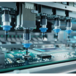
Feeder Maintenance and Tape Handling on the SMT Line
A placement machine is only as good as the tape it draws from, and most intermittent placement defects trace back to a feeder that has drifted rather than to the head. Feeder care is unglamorous maintenance with a direct effect on yield.
How a Feeder Presents a Part
The tape is indexed forward by a sprocket that engages the carrier holes, and the cover tape is peeled away as the tape advances. The part pocket arrives at a fixed pickup position, and the nozzle descends to take the part.
Every one of those actions has a tolerance. The sprocket pitch, the tape width, the pocket position within the tape and the height of the tape in the track all contribute to where the part actually sits.
The machine compensates for a constant offset with a vision or mechanical centring step, but it cannot compensate for variation between picks. Variation is what produces intermittent placement defects.
Wear and Its Symptoms
Worn sprocket teeth allow the tape to advance slightly more or less than one pitch, and the error accumulates along the reel. The symptom is a placement offset that grows as the reel is consumed.
A worn peel bar or a damaged cover tape path produces a cover tape that peels unevenly, sometimes lifting the part out of the pocket and sometimes leaving it partly covered.
A weak spring or a stiff tape path produces unreliable indexing at speed, appearing as skipped pockets where the nozzle picks nothing. Our inspection notes describe how a missing part appears at the inspection station.
Tape Handling Practices
Tape should not be bent, crushed or stored in a way that deforms the pockets. A reel that has been squeezed in a bin has pockets that no longer hold the parts at a consistent height.
Reels that are partly consumed should be stored in a way that keeps the remaining tape from unspooling and stressing the carrier. An unrestrained reel that has spilled inside its box will not feed reliably.
Splices should be made with the correct splice tape and the correct alignment, because a splice that is slightly offset produces an indexing error at that point and nowhere else. A reinforced splice tape that is too thick can jam the track.

The Pickup Position
The pickup position is a parameter of the program, and it should be verified when a feeder is loaded rather than assumed. The verification is a visual check or an automated one on the first few picks.
The height of the nozzle at pickup determines how far the nozzle descends. Too high and the part is not captured; too low and the part is pressed into the pocket and can be damaged.
Where the same part is loaded in several feeders, each feeder has its own pickup position. Using one value for all of them treats variation between feeders as if it did not exist. Our quality notes describe the first article checks that detect the resulting error.
Maintenance Schedule
Feeder maintenance is a routine: cleaning the tape path, checking the sprocket for wear, checking the spring tension, and verifying the pickup position on a test tape. The interval should be based on the number of placements rather than on the calendar.
Feeders that have been dropped should be checked before they are used again, since a bent frame changes the pickup position in a way that cannot be seen from outside.
The maintenance record should identify each feeder by its serial number, so that a feeder with a recurring problem can be taken out of service rather than repaired repeatedly. Our design release checklist notes where the equipment records belong in the process documentation.
Program and Setup Data
The program should record, for each part, the feeder type, the tape width, the pitch, the pickup position and the nozzle. This is the data that makes a later build reproducible.
Where a part is second sourced and the tape dimensions differ, the feeder data must be updated. A reel with a different pitch loads into the same slot with a different setting.
The setup sheet should be checked against the physical line as part of the changeover. Our solder defects notes describe the assembly faults that appear when a feeder presents the wrong part.
Detecting a Feeder Problem
The signature is a defect that appears on a single part number, concentrated in one feeder position, and not on the same part number loaded elsewhere.
A second signature is a defect rate that changes over the life of a reel, which points at the sprocket or the tape rather than at the machine.
Swapping the feeder to another slot and observing whether the defect follows it is the definitive test, and it takes a few minutes. The result should be recorded so that the feeder is repaired rather than swapped indefinitely.
Process Control and Verification
On a design of this kind, pickup position is the item that decides how the rest of the board is arranged. A short note on the drawing about handling, storage or packaging is often worth more than an extra decimal place on a tolerance. Where a value sits close to a process limit, the drawing should say so, since the shop can then open the process window rather than working to a nominal figure that carries no tolerance.
A stack-up that is drawn rather than described removes most of the ambiguity from a quotation, and it lets the fabricator price the board against the dielectric and copper weights that will actually be used. Where the requirement is not written down, the shop supplies its own default, and the default is chosen for the process rather than for the design.
The measurements that matter are the repeatable ones: conductor width and spacing, annular ring, finished hole size, plating thickness and surface finish are all verifiable on a coupon that travels with the panel.
Process Control and Verification
On a design of this kind, pickup position is the item that decides how the rest of the board is arranged. A short note on the drawing about handling, storage or packaging is often worth more than an extra decimal place on a tolerance. Where a value sits close to a process limit, the drawing should say so, since the shop can then open the process window rather than working to a nominal figure that carries no tolerance.
Process Control and Verification
On a design of this kind, pickup position is the item that decides how the rest of the board is arranged. A short note on the drawing about handling, storage or packaging is often worth more than an extra decimal place on a tolerance. Where a value sits close to a process limit, the drawing should say so, since the shop can then open the process window rather than working to a nominal figure that carries no tolerance.
FAQ
How often should feeders be serviced? On a placement count basis rather than a calendar basis, because wear is driven by use and by the tape being handled.
Can damaged tape be used? The damaged section should be removed and the tape respliced, because the pockets in that section will not present parts reliably.
What does gopcb provide for feeder control? We provide feeder setup sheets with the tape and pickup data for each part, maintenance records by feeder serial number, first article verification of the pickup positions, and a defect investigation procedure that follows the defect to the feeder.