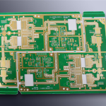
Panelisation For Small Boards: Rails, Fiducials, Spacing
A board that is smaller than the assembly line can handle has to be built as part of a larger panel. The panel is what the machine grips, the conveyor carries and the stencil prints through, and the small board is separated from it at the end. Panelisation is the design work that makes that possible, and it is usually done late, when the board outline is already fixed and the space is already tight.
This article explains why small boards need a panel at all, what the panel has to include, and which of those features should be decided early.
The awkward part is that the features which make a board manufacturable frequently belong to the panel rather than to the product, so they are easy to treat as someone else’s problem.
Why The Line Has A Minimum Size
Surface mount equipment is designed around a range of board sizes, and boards below roughly sixty millimetres square fall outside the comfortable part of it. Transport is the first reason: the conveyor rails hold the board by its edges, and a very short board may not bridge the gap or may tip as it moves between stations. Placement accuracy is the second, because a small board is less stable under the nozzle and any movement becomes a placement error at a fine pitch.
Heat is the third reason. A small board has little thermal mass, so it heats and cools quickly in the oven, which makes the profile harder to control and increases the risk of a component seeing more heat than intended. A panel with several copies of the board and a surrounding frame changes all three of those conditions at once, which is why panelisation is the standard answer rather than a special technique. The decision affects how the board is produced as much as how it is designed.

Rails And Process Edges
The rail is the strip of material along the edge of the panel that the conveyor grips and the machine references. It is not part of any product, and it has to be wide enough for the rails of the equipment, typically five to ten millimetres, and long enough to give the panel a size the line can accept. Holes or notches in the rail locate the panel in the machine, and their position and diameter are set by the equipment rather than by the design.
The rail is also the surface that carries the panel through printing, so it has to be flat and it must not interfere with the stencil. Where the panel is printed with a stencil that covers the whole area, the rail takes paste that is never used, which is a small waste of material rather than a problem. The process edge should be free of vias and copper that would create a step, and the panel has to stay flat after lamination and after reflow, because bow and twist are measured across the panel rather than across the product.
Fiducials And Panel Tooling
Every machine that places or inspects a component needs a reference, and the fiducial is it. Two or more global fiducials on the panel give the machine a coarse alignment, and local fiducials near fine pitch components give it the accuracy those parts need. The fiducial is a copper dot with a clear area around it and no solder mask over it, and its size and the clearance around it are specified by the equipment rather than chosen for convenience.
Local fiducials matter more on a panel than on a single board, because the panel can distort slightly between the areas where the parts are concentrated. Placing a pair near each group of fine pitch components lets the machine correct for that locally, which is the same principle used to compensate for material movement. The guidelines for a manufacturable layout cover the fiducial requirements alongside the other panel features.

Separation: Tabs, Score Lines And Routing
How the individual boards are separated from the panel decides both the edge quality and the freedom of the layout around it. A routed slot with a set of small breakaway tabs is the most flexible method: the router cuts most of the outline and the tabs hold the board in place, and the board is snapped out afterwards. The tabs leave small marks where they break, which has to be acceptable at that part of the edge.
A V score is a partial cut through the material along a straight line, and the board is broken along it. It is faster and cheaper, and it produces a cleaner edge, but it only works along a straight line and it consumes a strip of board surface on either side. Where the edge is irregular, or where components must sit close to the edge, routing with tabs is the practical choice. Both methods put mechanical stress into the board when it is separated, and that stress is why components should not be placed within a defined distance of the separation line. The rules for what can sit near a board edge or a slot are described with the routing allowances for slots and edges.
Component Clearance And Keep Out
The component clearance is the space around the separation line that has to stay free of parts. A tall component near a V score can be damaged when the board is broken, and a component close to a routed edge can be struck by the router or cracked by the stress of snapping a tab. The distances depend on the separating method and on the height of the parts, and they should be stated in the panel drawing rather than left to the assembly house.
There is a second clearance to consider on the other side of the panel. The area above the rail and around the tabs must be clear for the machine and the conveyor, so a component that overhangs the board outline can foul the equipment even if it is inside the product boundary. This is the kind of requirement that is cheapest to satisfy when the layout is being planned, and most expensive when it is discovered by the assembly house.
Panel Size, Density And Cost
The number of boards on a panel is a compromise. More copies per panel reduce the machine time per board and the material wasted in the rails, but a large panel is more likely to sag in the oven and more costly to replace if one area is bad. The panel also has to fit the equipment, which imposes both a maximum and a minimum dimension.
The cost of the panel is not only the material. Extra area in the rails, tooling holes and fiducials is area that produces no product, so a panelisation that is generous with space costs money on every unit. A panel that is too tight produces yield problems instead. The useful approach is to define the panel with the assembly house, using their equipment limits and the quantities actually being built, and to check that the result is compatible with the rest of the fabrication requirements. gopcb prepares panels for small boards with rails, fiducials and the separation method that suits the outline, and adjusts the arrangement to the equipment the customer’s line uses.
FAQ
Can a very small board be assembled without a panel? Some equipment can handle it with a fixture, but placement accuracy and thermal control are both worse. A panel is usually cheaper and more reliable.
Which separation method is best? It depends on the edge. A V score is cheaper and cleaner but only works on a straight line; routing with tabs handles any outline at the cost of small marks.
How close can a component be to the separation line? It depends on the method and the component height. The distance should be specified on the panel drawing rather than assumed.