Flash Plating Control for PCB Copper Surfaces: 5 Rules
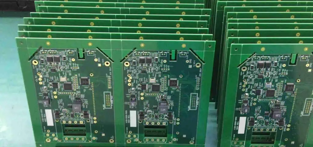
Flash plating is a short electrolytic plate that puts a thin layer of copper over a surface before the main plating step. It is used to protect a freshly activated surface from oxidation, to establish a continuous conductive path, and to give the main deposit something uniform to build on.
Because it is thin, it is easy to treat as a formality. In practice the flash is the layer that decides whether the subsequent copper is continuous, whether the adhesion holds through thermal stress, and whether a small defect in the surface becomes a void in the finished barrel.
What Flash Plating Does
The first function is protection. Between the activation step and the main plating bath there is a transfer, and any surface that is exposed to air in that interval begins to oxidise. A flash applied immediately after activation covers the surface before oxidation starts.
The second function is conduction. The flash provides a continuous conductive path across the surface and into the hole, which is what allows the main plating current to be distributed evenly rather than concentrating at the entry.
The third function is nucleation. The main deposit grows on the flash, so the grain structure and the uniformity of the thin layer carry into the thicker one. A flash that is patchy produces a plating that is patchy at a larger scale.
Thickness and Current Density
Flash thickness is usually specified in the range of a fraction of a micron to a few microns, and it is controlled by current density and time. Because the two are interchangeable in principle, the shop sets a current density that produces a sound deposit and then varies only the time to change the thickness.
Current density has an upper limit set by burning. Above it, the deposit becomes powdery and dark at the edges of the panel, and the adhesion of the main plating to that powder is poor. The throwing power discussion explains how the current distributes across a panel and into a hole.
Thickness is verified by weight gain on a coupon or by X-ray fluorescence on a plated surface, and the measurement is taken at several points because the flash is naturally thicker near the contact points.
Surface Preparation Before the Flash
A flash cannot repair a surface that was not prepared. Oxide, resist residue, fingerprints and dried conditioner all prevent the deposit from bonding, and each of them produces a different defect: oxide gives a blistered deposit, residue gives a skip, and oil gives a dark stain that plates weakly around its edge.
The rinse between activation and flash is therefore a critical stage, and its quality is judged by conductivity or by a water-break test rather than by appearance. Carry-over from the previous bath changes both the pH and the conductivity of the flash bath.
Where the panel has been handled between the two, the fingerprints are visible in the plated result, which is why the transfer is usually automated or done with clean gloves and a defined route.
Adhesion and the Plating Window
Adhesion is tested by thermal stress: the coupon is baked and then dipped in molten solder, and the plated surface is examined for blistering and lifting. A flash that was applied over a contaminated surface fails this test even when the thickness is correct.
The window between activation and flash is time-limited. Every minute of transfer adds oxide, so the sequence is arranged so that the flash bath is the next tank, and the panels move in a train rather than being allowed to queue.
Where a line cannot arrange that, the activation is strengthened and the transfer is shortened, and the result is verified more frequently. The plating void notes describe how the failure appears in a barrel.
Rinse, Dry and Oxidation
After the flash the panel is rinsed and dried before the main plating or before storage. The rinse removes dragged-out chemistry, and the dry prevents water marks that would later appear as stains under the main deposit.
A panel that is stored after the flash should be stored dry and in a way that does not allow the surface to oxidise, because the flash is too thin to survive a long exposure. Where the interval is long, the flash is normally omitted and the sequence is arranged so that activation and plating happen together.
The heavy copper notes describe how the main deposit is controlled when the current and the time are much larger, and the condition of the anodes that supply the copper is covered in the anode bag guide.
Verification and Records
Coupons plated with every load give a thickness and an adhesion result for that load, and a trend across coupons shows a bath that is drifting before a panel is affected. The coupon should be placed where the current density matches the panels it represents.
Records should include the current, the time, the bath analysis, the temperature and the coupon result, because a flash that fails is usually explained by one of those five values rather than by the material.
Where a defect is found later, in the barrel or under the main deposit, the flash records are what allow the cause to be separated from the main plating parameters.
Coupon Placement and Bath Interaction
Copper thickness on the coupon is only meaningful if the coupon saw the same current density as the panel it represents. A coupon placed at the edge of the rack plates thicker than one in the middle, and the difference can exceed the tolerance of the flash itself.
The flash bath also interacts with the previous tank. Drag-in of activator raises the pH and consumes the bath more quickly, while drag-in from the following tank changes the conductivity. Both effects appear as a copper thickness that falls through the working day.
Agitation belongs to the same picture. A still bath develops a depleted layer at the surface, and the deposit becomes thinner and rougher where the flow is poor. Air agitation or cathode movement is therefore part of the plating specification rather than a convenience.
Where a line plates several panel types, the current is set from the surface area rather than from the number of panels. Using a fixed current for every product is the commonest cause of a flash that burns at the contacts and is thin everywhere else.
Thickness uniformity across a panel is verified by measuring at several points rather than at one. A result taken only at the centre hides the edge build-up that causes burning, and a result taken only at the edge hides a thin deposit in the middle.
Where the flash is followed immediately by the main plate, the two deposits behave as one layer and the interface cannot be measured separately. The evidence for the flash is then the coupon result and the absence of voids in the barrel.

FAQ
Is a flash plate necessary if the main plating follows immediately? It is not always necessary on a well-controlled line, but it is the cheapest insurance against oxidation during transfer. Where the line is long or the transfer is manual, the flash earns its place.
Why does the flash look darker at the panel edges? Because the current density is highest there. The deposit is thicker and coarser at the edge, and if the effect is strong the current has to be reduced or the contacts rearranged.
Can flash thickness be judged by colour? Roughly, by an experienced operator, but not for release. Colour indicates a trend, while weight gain or fluorescence gives a number that can be compared with a specification.