
FPC Outline Design: Tolerances, Cutting and Panel Layout
The outline of a flexible circuit is not a rectangle drawn around the circuit for convenience. It is a mechanical element that decides how the part is made, how it is handled and, in many products, how long it survives in service.
A flex circuit can be any shape, which is both its advantage and the source of most of its manufacturing difficulty. The outline governs the cutting process, the panel layout and the stress distribution at every corner.
Why the Outline Matters on a Flex Circuit
On a rigid board the outline is usually cut by a router or a V-cut, and the shape is constrained by those processes. On a flex circuit the outline can be die cut, laser cut or routed, and the achievable tolerance and the tooling cost differ significantly between them.
The outline also determines how the part behaves mechanically. A narrow neck, a sharp internal corner or a long unsupported tongue all concentrate stress, and those features are far more significant on a thin flexible material than on a rigid laminate.

Outline Tolerance and Process Choice
Die cutting is fast and cheap at volume, with a tolerance that depends on the die and on the material. Laser cutting needs no hard tool, holds a good tolerance and suits prototypes and low volumes, while routing is used where the shape or the thickness makes the other two impractical.
The tolerance has to be chosen against the function. Where the outline locates the circuit in a housing, the tolerance is mechanical and must be tight. Where the outline is simply the edge of a part that is bonded onto a surface, a looser tolerance is usually acceptable.
Die Cutting, Laser Cutting and Routing
A die cuts by shearing the material, which works well for thin stacks and produces a clean edge in volume. The tool cost is significant, so a design change after the die is made is expensive, and the design should be frozen before the tool is ordered.
Laser cutting vaporises the material along a path. It requires no tool, it can follow any contour and it holds a tolerance of roughly 0.1 mm on a typical flex stack, but it leaves a slight taper and a heat affected edge that has to be considered where the edge is bonded.
Corners, Radii and Stress Risers
An internal corner with a sharp radius concentrates stress, and a flex circuit will tear from that point long before the copper or the coverlay fails elsewhere. A radius of at least half the material thickness, and preferably more, distributes the load.
External corners matter as well, though less severely. A generous radius reduces the chance of a crack starting at the edge and makes the part easier to handle without the corner curling.
Panel Design and Handling
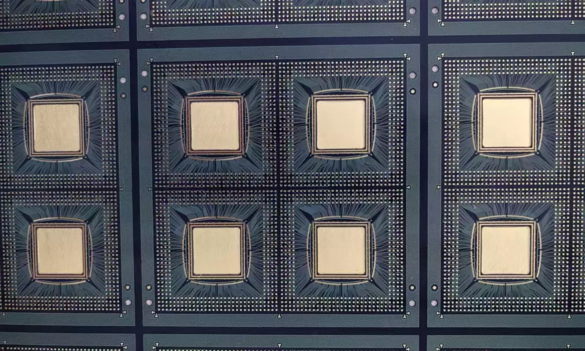
Flex circuits are usually produced in panels with several parts held by tabs or in a frame, and the panel design decides how the parts are handled through the laser, the plating line and the assembly process.
The tabs should be placed where they do not interfere with the assembly and where they can be cut without stressing a bend area. Fiducials for the assembly machines belong on the panel rather than on the individual part, since the part may be too small to carry them.
Slits, Tabs and Folding Features
Where a flex circuit has to fold, the outline can include a slit or a pair of relief cuts that allow the material to bend without puckering. The slit terminates in a radius rather than a point, for the same reason that an internal corner does.
A folding feature also changes the length of the circuit. When a flex is folded, the neutral axis stays the same length while the outer surfaces compress and extend, so a route that is measured flat will be slightly different when folded. Where the length matters, the design is checked in the folded state rather than the flat one.
Adhesive and Coverlay at the Edge
The coverlay and the adhesive layers are patterned with their own margins relative to the outline. Coverlay that extends beyond the cut line is trimmed during cutting, while coverlay that stops short of the outline leaves the conductors exposed at the edge.
For a circuit that is bonded to a surface, adhesive is applied in a pattern that stops short of the outline so that it does not squeeze out during lamination. That border is usually between 0.2 and 0.5 mm and is a design decision rather than a process detail.
Inspection and Common Defects
Inspection covers the outline dimension, the condition of the edge and the presence of any burr, delamination or discolouration from the cutting process. A laser cut edge has a slight taper, and a die cut edge has a shear mark, and both are normal within limits.
The defects that matter are a torn corner, an edge that has delaminated between the coverlay and the base film and a cut that has reached a conductor. gopcb produces flex and rigid-flex circuits with die cut, laser cut and routed outlines, and can advise on the corner radii, tab positions and adhesive borders that keep a part manufacturable.
Design Rules and Checklist
Give every internal corner a radius, keep conductors and coverlay boundaries away from the cut line, place tabs where they can be cut without stressing a bend, and choose the cutting process from the tolerance and the volume together.
Then check the folded state. A part that is dimensionally correct when flat can still be wrong when it is installed, and the outline and the routing both have to be verified in the shape the product actually uses.
How the FPC Outline Interacts with Assembly
The outline is the reference that the assembly machine uses to place the part, so an FPC outline that varies from piece to piece produces a placement error that no amount of vision correction can remove. Where the part is placed in a carrier, the carrier provides the reference and the outline tolerance can be relaxed, which is one of the practical reasons carriers are used for small flexible parts.
The outline also defines the area available for a stiffener, a connector or an adhesive patch. A stiffener that runs to the edge of the part can be exposed at the cut and lift under load, while one that stops short leaves an unsupported border that flexes. The outline, the stiffener and the coverlay boundaries are therefore drawn together and reviewed as a single mechanical interface.
Determining the Corner Radius
The corner radius is chosen from the material thickness and from the load the feature will see. A rule of thumb is a radius of at least half the total flex thickness for a static part, and a considerably larger value where the corner is loaded or where the part is handled repeatedly during installation.
The process also sets a floor. A die cannot produce an internal radius smaller than its own tooling allows, and a laser can produce a sharper corner but leaves a heat affected zone that weakens the material at that point. Where the mechanical requirement calls for a very small corner radius, the design usually changes the shape instead, replacing the corner with a curve or moving the feature away from the highly stressed region.
FAQ
What tolerance can a flex outline hold? Around 0.1 mm for laser cutting and tighter for a well maintained die. The requirement should come from the function rather than from a default value.
Can a flex circuit have an internal cutout? Yes, and it is common for a connector window or a mounting feature. Internal corners still need a radius, and the cutout has to be reachable by the cutting process.
Why do flex circuits tear at corners? Because a sharp corner concentrates stress. A radius spreads the load over a larger area and removes the initiation point for a crack.
Related reading: rigid-flex PCB design, FPC stiffener comparison, board outline and mounting design, and PCB routing precision.