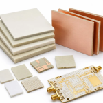
FR4 vs Rogers for RF Modules
Why the Laminate Decides RF Performance
At low frequency the copper does the work and the dielectric is a mechanical support. At radio frequency the dielectric becomes part of the circuit. Its permittivity sets the impedance of every trace and the physical length of every matching element, and its loss tangent decides how much of the signal is converted into heat before it reaches the antenna. Choosing between FR4 and a PTFE-based material such as the Rogers families is therefore not a purchasing decision, it is a design decision, and the two materials lead to different boards.
Dk, Df and What They Change
The dielectric constant, Dk, sets the relationship between a trace geometry and its characteristic impedance, and it also sets the guided wavelength. A material with a Dk of 4.3 produces shorter traces for the same electrical length than one with a Dk of 3.0, which matters for every quarter-wave stub, matching network and filter. The dissipation factor, Df, describes how much energy the dielectric absorbs. Standard FR4 sits around Df 0.015 to 0.02, while a low-loss PTFE-based laminate sits an order of magnitude lower, in the region of 0.001 to 0.002. That difference is small on a short interconnect and decisive on a long line, a filter with a narrow band, or any path that runs at 5.8 GHz and above.
Where FR4 Still Works Well
FR4 remains a reasonable choice for a great many radio designs. At 2.4 GHz, on a path of a few centimetres, with a link budget that has margin, the extra loss of FR4 is a fraction of a decibel and is invisible in practice. Consumer devices with a short antenna feed, low data rates, or heavy digital content on the same board generally do well on FR4, and the material brings process advantages: it is cheap, widely available, well characterised for multilayer build-up, and it behaves predictably through reflow.
Where FR4 Breaks Down
Three conditions push a design off FR4. The first is frequency, generally above 6 GHz, where the loss per unit length rises quickly. The second is long lines at high frequency, such as a backplane feed or a phased array manifold, where the loss accumulates with length rather than with frequency alone. The third is the need for a stable Dk: FR4 varies with resin content and with glass weave, so a trace that is meant to be a precise phase length can drift, and impedance can vary across a panel. Where a design needs tight impedance control on a fine line, the weave effect on FR4 is itself a source of variation.

What Low-Loss Laminates Offer
PTFE-based materials provide a low and stable Dk, a very low Df and much better thickness and Dk tolerance. The cost is in the processing. The material is softer, it needs different drilling parameters, it needs a plated through-hole process that is tuned for the surface, and it usually needs a different lamination cycle. Where the stack mixes PTFE with FR4, the two expand differently and the drill registration between them becomes a design constraint. A manufacturer who is familiar with the material will hold the tolerance; one who is not will produce boards that pass continuity and fail on insertion loss.
Mixed Dielectric Builds
A common and efficient compromise is to use low-loss material only where the radio actually lives. The RF layers and the antenna feed are built on the low-loss core and the digital and power layers stay on FR4, bonded in one stack. This controls cost and keeps the RF performance, but it requires the layout to respect the boundary: the transition from one dielectric to the other is an impedance discontinuity and should be modelled, not assumed, and the layer assignment has to keep the reference plane continuous across the transition.
The Cost Question
The material itself is only part of the cost difference. Low-loss laminates cost more per panel, but they also demand tighter process control, more careful drilling, often a higher layer count for the same routing, and sometimes a separate qualification run. The honest comparison is not price per square metre against price per square metre, but the cost of the whole board including the yield. On a product where the radio is a small part of a dense design, the mixed stack almost always wins; on a pure RF board, the low-loss material often ends up cheaper once the yield on FR4 is counted.
Measuring the Result
Because the electrical outcome depends on the finished geometry, verification should be geometric rather than visual. A cross section through a coupon on the panel shows the actual sidewall angle, the base width and the copper thickness, and it is the only measurement that captures the trapezoid that the impedance model has to account for. Coupon-level impedance testing then confirms whether the assumption held. Where the process drifts, the drift usually appears first in the etch factor as the bath ages or the spray nozzles wear, which is why the coupon should be taken from the same panel as the product rather than from a separate qualification run.

FAQ
Is FR4 ever good enough for RF? Yes, particularly at 2.4 GHz with short feed lines and adequate link margin.
What Df should I look for? A low-loss laminate sits near 0.001 to 0.002, an order of magnitude below the 0.015 to 0.02 typical of standard FR4.
Does Dk only affect impedance? No. It also sets the guided wavelength, so every matching element changes length when the material changes.
Can I mix the two materials? Yes, and it is a common way to control cost. The dielectric transition must be modelled and the reference plane kept continuous.
When should I definitely move off FR4? Above roughly 6 GHz, on long high-frequency runs, or where Dk stability across the panel is critical.
Conclusion
The material choice follows from the frequency, the line length and how much margin the link has, not from a preference for a brand. Model the loss on the actual stack, decide whether Dk stability is a requirement, and consider a mixed build before paying for low-loss material on layers that carry only digital signals. Material and stack-up options are listed under PCB capabilities, the fabrication consequences of each laminate are described in PCB manufacturing, and the impedance and layer decisions are made in PCB design and layout. Radio modules are normally characterised during a prototype PCB assembly build in 2026.