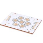
Gap Filler Dispensing for High Power PCB Assemblies
Many power assemblies have a gap between a component and its heat sink that is too wide or too uneven for a thin thermal interface material to bridge. A gap filler is a soft, heavily loaded polymer dispensed into that space, where it conforms to both surfaces and carries heat away. It solves a genuine thermal problem, but it also imposes new constraints on dispensing, clamping and long term stability.
Why Gap Filler Is Used
A thermal interface material only performs as intended where two surfaces are flat, parallel and close together. Machined housings rarely meet that ideal, and a stamped heat sink is worse. Where the gap exceeds roughly half a millimetre, or where it varies across the component, a preformed pad cannot follow the geometry and air stays trapped in the interface.
Gap filler is chosen when the interface is defined by mechanical reality rather than by ideal geometry. The gap may vary from one side of a package to the other, the surfaces may not be parallel, and the assembled stack carries tolerances from the board, the component, the fasteners and the housing. A dispensable material accommodates all of that in a single operation. It is common on high power assemblies, where the copper that carries the circuit current also has to move heat out of the board.
How Heat Moves Through a Filled Gap
Heat crosses a filled gap in three stages. It conducts from the component into the filler, travels through the bulk of the material, and then passes into the heat sink. The bulk term depends on the thermal conductivity of the compound and on the thickness of the layer, so a modest gain in conductivity can be cancelled by a thicker bond line. The substrate also matters, and the trade offs between metal core and ceramic boards decide how much heat reaches the gap in the first place.
The two contact resistances at the surfaces usually dominate. A material that wets both surfaces and displaces the air film performs better than its bulk rating suggests, while a compound that does not wet leaves microscopic voids that block the path. Surface condition and clamping force therefore matter as much as the quoted figure, as discussed in this guide to thermal management.
Gap Filler Versus Gap Pad
A gap pad is a preformed sheet with a defined thickness, supplied in die cut shapes. It is clean to handle, needs no dispensing equipment, and gives a repeatable bond line as long as the gap matches the pad. It is also the better choice for field service, because a pad can be replaced without metering or mixing anything.
A gap filler is dispensed, so it conforms to whatever gap exists and can be applied to a narrow cavity or an irregular outline. It handles large and variable gaps that no pad can bridge, and it can sometimes be applied after assembly through a port. The trade off is process control, because volume, mixing ratio and cure all have to be managed.
Chemistry and Filler Loading
Most gap fillers are silicone based, because silicone stays soft over a wide temperature range and resists thermal ageing. Polyurethane systems offer better adhesion and mechanical toughness at lower cost, and epoxy systems provide the strongest bond where the joint is structural. The choice is set by the temperature range, the clamping method and the rework policy.
Thermal conductivity comes from the filler, usually alumina, boron nitride or zinc oxide. Raising the loading improves conductivity but increases viscosity, and a material that is too stiff will not flow into a thin gap or conform under modest pressure. Formulators trade these properties against each other, which is why two products with the same conductivity rating can behave very differently on a dispenser.

Dispensing Equipment and Patterns
Two part materials are usually delivered by a meter mix system that ratios the components, mixes them in a static mixer and dispenses the result. Single part materials can be applied from a cartridge with a piston or auger pump. The mixing ratio, the mixer life and the shot volume are the parameters that decide whether the deposit is correct.
The dispense pattern matters as much as the volume. A single large dot traps air when the parts close, while a serpentine or multi dot pattern lets the material spread outward and push air ahead of it. The target volume is calculated from the gap, the area and a small allowance for squeeze out, and it should be verified by weighing a sample deposit.
Compression, Bond Line and Clamping
Once the parts are clamped, the filler is squeezed into a thin layer. Bond line thickness controls the thermal resistance, so it is a process parameter rather than an outcome. Clamping force, stop height and the compressibility of the material together set the final thickness, and a hard stop is the most reliable way to repeat it.
Over compression pushes material out of the interface and can starve one corner while flooding another. Too little compression leaves a thick layer and a high thermal resistance. The clamping arrangement should be designed so that the filler is compressed within the range its data sheet allows, and the force should be controlled rather than estimated by feel.
Pump Out, Bleed and Dry Out
Repeated heating and cooling makes the bond line expand and contract, and a soft material can be gradually squeezed out of the interface. This pump out effect raises thermal resistance over time. A formulation with higher cohesion, a filler that resists migration and a joint that is mechanically constrained all slow the process down.
Low molecular weight fractions in the polymer can migrate out as a thin film, which contaminates nearby surfaces and can affect electrical performance. At high temperature, volatile fractions leave and the material hardens, a process called dry out. Selecting a formulation with low bleed and low volatile content is the practical defence.
Curing, Rework and Serviceability
Cure schedules range from a few minutes at elevated temperature to several hours at room temperature. A heat cure gives better properties but stresses the assembly and may move components, while a room temperature cure is gentler but slower and can be disturbed before it has set. The schedule should come from the material data sheet and be verified on the line.
Serviceability is decided at the design stage. A cured silicone can often be cut away and replaced, while a structural epoxy joint usually cannot be opened without damage. Where a module must be repaired, a soft formulation and a mechanical interface that can be separated are worth more than a small gain in conductivity.
Specification, Test and Qualification
A specification should quote the bulk thermal conductivity, the intended bond line thickness, the hardness or compression behaviour, the compression set, the dielectric strength and the operating temperature range. Stating a conductivity figure without the bond line it was measured at is meaningless, because the two are coupled in the finished joint.
Qualification should reproduce the real joint. A test stack with the production gap, the production clamping and the production cure will show pump out, bleed and dry out that a flat coupon test never reveals. Thermal cycling, power cycling and a long soak at the maximum temperature expose the failure modes that matter, and the results should be checked against the component tolerance and reliability assumptions used at design.
FAQ
How thick should a gap filler bond line be? Thin is better for thermal performance, and most materials are rated for a compressed thickness of roughly 0.1 to 0.5 mm. The limit is set by the smallest gap the material can fill without voids and by the compression range in the data sheet, so the target comes from the material rather than from the thermal calculation alone.
Can gap filler replace a gap pad? In many designs it can, and it is the better choice when the gap is large or variable. A pad remains preferable where a defined thickness is needed, where field replacement matters, or where dispensing equipment and the process control that goes with it are not available.
Why does thermal performance drop over time? Usually because of pump out, bleed or dry out. The bond line thins unevenly as the material is squeezed out during thermal cycling, volatile fractions leave at high temperature, and the interface develops voids. A more cohesive formulation and a mechanically constrained joint slow all three.