Hot Bar Soldering: Thermode Choice and Fine Pitch Joints
Hot bar soldering joins a row of fine pitch connections in one operation by pressing a heated metal tool onto the joint area, and it is the standard method for attaching a flex tail to a rigid board. The tool transfers heat by conduction rather than by air, so the process is fast and local, but it also means the geometry of the tool and the flatness of the parts decide whether the joints form at all.
How Hot Bar Soldering Works
A thermode, which is a metal bar with a defined tip profile, is brought down onto the solder or the pre-tinned surfaces with a controlled force. Current is passed through the thermode to heat it, the solder melts and wets, and the bar is then cooled or lifted so that the joint solidifies while it is still being held flat.
The whole cycle is usually a few seconds, which is short enough to protect the parts from the thermal exposure of an oven. That short cycle is the reason the process is used for connectors, shielded cables and flex tails that cannot survive a reflow profile on their own.
Thermode Geometry and Material
The thermode tip has to match the joint pattern, so it is made for the specific product with a flat or a slightly crowned face and a width that covers the row without touching anything else. A tip that is too wide marks the adjacent mask, and one that is too narrow leaves the ends of the row cold.
Material selection matters because the bar has to heat quickly, hold its shape and resist oxidation. A coating that wears through changes the heat transfer, and the change is gradual enough that it is usually noticed as an unexplained rise in defective joints rather than as a tool failure.

Temperature, Force and Dwell
Three parameters define the process: the set temperature of the thermode, the force applied and the dwell time at temperature. They interact, so an increase in force can compensate for a lower temperature up to a point, and beyond that point the excess force damages the parts instead of helping.
The temperature at the joint is never exactly the thermode set point, because heat has to pass through the flex, the copper and the solder. The useful figure is the interface temperature, and it is measured with a thermocouple on a test sample rather than read from the controller display.
Fine Pitch Joints and Tool Alignment
At fine pitch the tolerance for misalignment is small, so the machine has to locate the part accurately and the thermode has to sit parallel to the row. Any tilt produces a joint that is hot at one end and cold at the other, and the cold end appears as an open connection at test.
Planarity is the other half of the same problem. A flex circuit that is not flat, a board with a bow in it, or a support that does not hold the assembly rigid will each prevent the bar from contacting the full row at once. The support fixture is therefore part of the process rather than an accessory.
Flex Circuits and Rigid Flex Applications
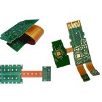
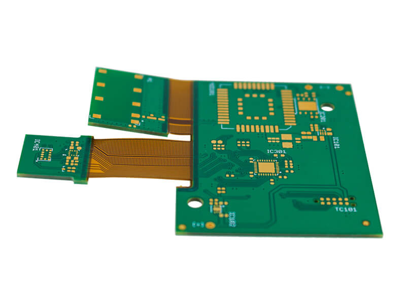
Flex tails are the classic application, because the polyimide film cannot tolerate a long thermal excursion and the copper is thin. Hot bar soldering delivers the heat where it is needed and lets the rest of the circuit stay cool.
The same method joins rigid flex sections, small ribbon cables and shielded assemblies where a connector would add height and cost. In each case the design has to leave enough exposed pad for the bar and enough clearance for the thermode body. Our bendable circuit materials notes describe the films involved.
Flux, Paste and Preform Options
The solder can come from a printed deposit, from pre-tinned surfaces, from a solder preform or from an anisotropic conductive film where the joint must also be an insulator between adjacent pads. Each option changes the process, and mixing them within one product family creates avoidable confusion.
Flux selection is critical because the flux has to activate quickly at a temperature that lasts only seconds. A flux designed for a long reflow soak may never reach its activation window in a hot bar cycle, leaving oxide on the surfaces and a joint that wets poorly.
Machine Setup and Process Control
The setup parameters should be recorded per product and locked, because a small change in force has a larger effect here than in a reflow oven. A machine that is adjusted by feel at each changeover will produce a different result on every shift.
Thermode temperature should be verified with an external meter rather than trusted from the display, and the force should be checked with a load cell when the tool is changed. Our thermal management notes describe how the heat spreads away from the joint.
Inspection and Joint Quality
The joints are visible, so visual inspection with magnification finds most of the defects. A good joint has a continuous fillet along the pad, a slightly concave profile and a smooth surface, while a cold joint looks lumpy and does not wet to the edge of the pad.
Pull testing on a sample is the objective check, and a cross section shows the interface condition when the visual result is ambiguous. Our solder defect notes describe the joint faults that also apply here.
When to Choose Hot Bar
Hot bar soldering is chosen when the joint is fine pitch, local and on a substrate that cannot take an oven cycle. It is not the right answer for a large connector with hundreds of pins, where a reflow or a press fit process is faster and more repeatable.
It is also a poor choice where the design cannot provide a flat, well supported joint area, because the process depends on contact. Where that support cannot be arranged, a different interconnect should be chosen at the design stage rather than at the assembly stage.
Process Control and Verification
On a design of this kind, fine pitch is the item that decides how the rest of the board is arranged. Keeping a sample from the panel turns a dispute into a measurement, because the same coupon can be re-examined by both parties without rebuilding the batch. Reviewing the design before the data is released is cheaper than correcting it after the panel is in the tank, because every step downstream inherits the decision made at the front end.
FAQ
Can hot bar soldering be used with lead free solder? Yes, but the higher melting point leaves a shorter process window, so the temperature, force and dwell have to be developed again rather than carried over from a tin lead process.
Is a thermode a consumable? It is. The tip wears and oxidises over thousands of cycles, and the change in heat transfer is gradual. Tracking the cycle count against the defect rate is the practical way to decide when to replace it.
How does gopcb support hot bar assembly? We leave the pad geometry the process needs, keep the flex flat and supportable, agree the solder source and flux with the customer, and qualify the profile on a sample with a thermocouple before production begins.