How to Program a PCB: PCB Design & PCB Manufacturing Guide
Printed circuit boards (PCBs) continue to evolve to support increasingly sophisticated electronic functions. The development of PCB technology was driven in part by the need to integrate electronic circuits into smaller, more organized physical structures. Early circuit boards were designed to perform relatively fixed functions according to predefined circuit logic.
As electronic systems became more advanced, however, fixed-function hardware was no longer sufficient for many applications. Modern electronic products often need to receive multiple inputs, process information, generate outputs, store data, and adapt their behavior through software.
This requirement led to the widespread use of programmable PCBs.
A programmable PCB typically contains a microcontroller, microprocessor, system-on-chip (SoC), or another programmable processing device. Its operating logic is provided by software or firmware stored in memory. Depending on the architecture, firmware may be programmed during manufacturing and later updated through a dedicated programming interface or a secure over-the-air (OTA) mechanism.
Learning how to program a PCB requires an understanding of both hardware and software. This guide explains the major steps involved in PCB programming, from component selection and PCB design to firmware development, programming, testing, debugging, and firmware updates.
Common Tools for PCB Programming
Programming a PCB requires a suitable hardware and software environment.
First, the PCB must contain a programmable device capable of executing firmware. Depending on the application, this may be a microcontroller (MCU), microprocessor (MPU), FPGA, SoC, or another programmable device.
Common PCB programming tools include:
- Development environment or IDE
- Compiler or build system
- Programmer or debug probe
- USB-to-serial interface
- JTAG interface
- SWD interface
- ISP interface
- Programming cables
- Debugging tools
- Target power supply
- Test fixtures
The exact tools depend on the processor architecture and development platform.
For example, ARM-based microcontrollers commonly support interfaces such as SWD or JTAG, while other microcontroller families may use proprietary or vendor-specific programming interfaces.
The programming software, device drivers, firmware tools, and programming hardware should be compatible with the target device and kept appropriately updated.
How to Program a PCB
Learning how to program a PCB generally involves selecting the right programmable device, designing the hardware, developing firmware, connecting a programmer, loading the firmware, and validating the finished system.
The following steps provide a practical overview.
1. Select the Appropriate Components
A programmable PCB requires a processing device and sufficient memory and peripheral resources for the intended application.
When selecting an MCU, MPU, FPGA, or SoC, consider factors such as:
- Processing performance
- Flash memory capacity
- RAM capacity
- Operating frequency
- GPIO count
- Communication interfaces
- ADC/DAC requirements
- Timers and PWM
- Power consumption
- Package type
- Operating temperature
- Development-tool support
- Long-term component availability
The instruction set and architecture of the processor also influence firmware development.
For beginners, it is often easier to start with a widely supported microcontroller family and an established development ecosystem.
Component selection should be based on the complete product requirements rather than programming considerations alone.
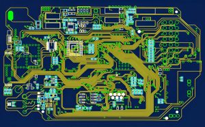
2. Design the Programmable PCB
Good PCB Design is essential for a reliable programmable system.
The microcontroller must be connected correctly to its supporting circuitry. Depending on the device, this may include:
- Power supply
- Ground
- Decoupling capacitors
- Reset circuit
- Clock or crystal circuit
- Boot configuration
- Communication interfaces
- Sensors
- Actuators
- Memory
- Debug/programming interface
The PCB should also provide a suitable programming or debugging interface.
For example, a development board may expose USB, SWD, JTAG, or serial interfaces through dedicated connectors. A production PCB may use a compact test header, pogo-pin fixture, or another manufacturing programming interface.
The programming interface should be designed with accessibility and manufacturability in mind. If firmware must be programmed during production, the board should provide a reliable method for connecting the programming fixture.
3. Develop the Firmware
The operating logic of a programmable PCB is provided by firmware.
Firmware is software designed to run on the target hardware. It may control sensors, communication interfaces, displays, motors, power-management functions, user interfaces, and other hardware resources.
Firmware is commonly developed using languages such as:
- C
- C++
- Rust
- Assembly
- Other processor-specific or higher-level languages
The appropriate language depends on the target platform and system requirements.
A typical firmware development process includes:
- Define functional requirements.
- Configure the processor and peripherals.
- Write the firmware.
- Compile the source code.
- Resolve compiler errors and warnings.
- Test individual functions.
- Debug hardware-software interactions.
- Generate the production firmware image.
The final firmware may be packaged in formats such as .hex, .bin, or vendor-specific formats, depending on the programming tool and target device.
It is important to distinguish the source code from the compiled firmware image. The source code is used for development, while the compiled image is what is normally programmed into the target memory.
4. Set Up the Programming Environment
Before programming the PCB, prepare the complete hardware and software environment.
Install the required:
- IDE
- Compiler
- Device drivers
- Programming utility
- Debugging software
- Programmer configuration files
Connect the programming probe or interface between the computer and the target PCB.
Before continuing, verify:
- Correct target device
- Correct voltage
- Correct programming interface
- Correct pinout
- Stable power supply
- Proper ground connection
- Correct driver installation
- Appropriate firmware version
The latest approved firmware should be obtained from the engineering or product team rather than using an unverified version.
5. Upload the Firmware
Once the programming environment is ready, connect the PCB to the computer through the appropriate programming interface.
The general process is:
- Power the target PCB.
- Connect the programmer or debug probe.
- Launch the programming software.
- Select the correct target device.
- Detect or connect to the target.
- Select the approved firmware image.
- Configure memory and programming options.
- Erase or prepare the target memory if required.
- Program the firmware.
- Verify the programmed data.
- Reset or restart the target device.
- Confirm that the firmware runs correctly.
Successful programming should normally be followed by a verification step. This confirms that the firmware image was written correctly rather than simply assuming that the programming operation completed successfully.
After verification, the programmer can be disconnected if the product does not require a permanent connection.
In high-volume PCB Manufacturing, this process can be integrated into a production programming station or automated test fixture.
6. Test and Debug the PCB
Programming is not complete simply because the firmware has been uploaded successfully.
The PCB should be tested under representative operating conditions to verify the interaction between the firmware and hardware.
Testing may include:
- Power-up testing
- GPIO testing
- Sensor testing
- Communication testing
- Display testing
- Motor or actuator testing
- Timing verification
- Memory testing
- Functional testing
- Fault-condition testing
- Temperature testing
Debugging interfaces such as JTAG or SWD can provide valuable information during development.
Engineers may also use oscilloscopes, logic analyzers, multimeters, electronic loads, and other test equipment to observe real-time behavior.
For production systems, automated functional testing can help identify incorrectly programmed boards, assembly defects, component problems, or firmware-hardware compatibility issues.
7. Update or Reprogram the Firmware
Firmware does not necessarily need to remain unchanged after the initial programming process.
During product development, engineers may reprogram the PCB repeatedly as bugs are fixed and new features are developed.
After production, firmware updates may also be supported.
Common update methods include:
- USB programming
- Serial bootloader
- JTAG/SWD programming
- ISP programming
- External programming fixture
- Secure OTA updates
The update mechanism depends on the product architecture.
For consumer and IoT products, OTA updates can allow authorized firmware releases to be distributed remotely. However, secure authentication, firmware integrity verification, rollback protection, access control, and appropriate user or device authorization should be considered before deploying remote updates.
A firmware update should never be treated as simply downloading arbitrary code to a connected PCB. Production systems should use controlled and verified firmware-release processes.
Manual vs. Automatic PCB Programming
There are two broad approaches to programming and updating PCBs: manual programming and automated or remote programming.
Manual Programming
Manual programming is common during development, prototyping, repair, and some production processes.
An engineer or technician connects a programmer to the PCB and uploads the approved firmware image.
This approach provides direct control over:
- Firmware version
- Target device
- Programming configuration
- Verification
- Debugging
For prototypes and small production runs, manual programming can be practical and flexible.
Automated Programming
High-volume PCB Manufacturing may use automated programming stations or production fixtures.
A fixture can position multiple boards consistently and connect programming interfaces through pogo pins or dedicated connectors. The manufacturing system can then automatically:
- Identify the board.
- Connect to the target.
- Program the approved firmware.
- Verify the programmed image.
- Record the result.
- Pass or reject the board.
Automated programming reduces repetitive manual work and can improve production traceability.
Remote Firmware Updates
Connected products may support remote firmware updates through network connectivity.
This is common in IoT, industrial, automotive, smart-home, and other connected applications.
However, remote updates require appropriate cybersecurity controls. A robust system may use signed firmware, encrypted communication, secure boot, version management, rollback mechanisms, and authentication.
These controls help prevent unauthorized or corrupted firmware from being installed on the PCB.
Key Tips for Successful PCB Programming
Several practical considerations can make PCB programming more reliable.
Check the Pin Configuration
Verify the programming interface pinout before connecting the programmer.
Incorrect connections can prevent programming or, in some cases, damage the target hardware.
Verify Power and Ground
Confirm that the PCB receives the correct supply voltage and that the programmer and target share the required ground reference.
Configure the Boot or Reset State Correctly
Some microcontrollers require a particular boot configuration, reset sequence, or bootloader mode before they can accept firmware.
Use the Correct Firmware Version
Firmware should be version-controlled and matched to the correct hardware revision.
A firmware image designed for one PCB revision may not operate correctly on another revision if the hardware has changed.
Keep Development Tools Updated
Use compatible versions of IDEs, compilers, device drivers, and programming utilities.
At the same time, production environments should use validated tool versions rather than automatically installing every new software release without qualification.
Add Status Indicators
LED indicators can provide useful visual feedback during development and troubleshooting.
For example, LEDs can indicate:
- Power status
- Programming status
- Boot status
- Communication activity
- Fault conditions
- Successful initialization
Use Test Fixtures
Production test fixtures can provide repeatable connections between programming equipment and PCBs.
A fixture can combine programming, functional testing, electrical measurements, and traceability into a single production workflow.
PCB Design and Programming Considerations
PCB programming should be considered during the initial PCB Design stage rather than added as an afterthought.
The hardware should provide sufficient access to programming and debugging interfaces while maintaining appropriate electrical and mechanical constraints.
Engineers should consider:
- Programming connector placement
- Test-point accessibility
- Programming interface routing
- Ground connections
- Power requirements
- Signal integrity
- ESD protection
- Boot configuration
- Production fixture compatibility
- Firmware update requirements
For high-volume products, the programming method can also influence manufacturing cycle time and production cost.
A well-designed programming interface can simplify both prototype development and production testing.
PCB Programming in Different Applications
Programmable PCBs are used across a wide range of applications.
Consumer Electronics
Microcontrollers and processors can control displays, buttons, sensors, power systems, communication functions, and user interfaces.
Industrial Automation
Programmable PCBs can control motors, sensors, actuators, communication networks, and industrial equipment.
IoT Devices
Connected PCBs may combine sensors, wireless communication, processing, and cloud connectivity.
Automotive Electronics
Automotive control units can use programmable processors for functions such as body control, power management, sensing, communication, and other electronic systems.
Medical Electronics
Programmable electronics are used in monitoring, diagnostic, control, and medical-device applications, where firmware validation and hardware reliability are particularly important.
Conclusion
Learning how to program a PCB requires more than simply uploading a .hex or .bin file. Reliable PCB programming begins with appropriate component selection and a well-engineered PCB Design, followed by firmware development, programming-interface design, controlled firmware loading, verification, and functional testing.
During development, programmers and debugging interfaces such as JTAG, SWD, USB, or ISP provide direct access to the target device. In production, automated programming fixtures can improve consistency and traceability. Connected products may additionally support secure firmware updates through network or OTA mechanisms.
For successful PCB Manufacturing, hardware and firmware should be treated as an integrated system. Correct pin configuration, stable power, compatible programming tools, controlled firmware versions, reliable test fixtures, and thorough verification all contribute to a dependable production process.
As electronic products become smarter and more connected, programmable PCBs will continue to play an important role in consumer electronics, industrial automation, automotive systems, IoT devices, and other applications. A solid understanding of both PCB hardware and firmware programming enables engineers to develop products that are easier to test, maintain, update, and scale.