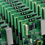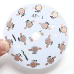
IC Programming is the process of loading firmware, configuration data, or application code into a programmable integrated circuit so that the device can perform its intended functions. It is widely used in the production of microcontrollers, microprocessors, FPGAs, CPLDs, memory devices, and other programmable electronic components.
An IC may be physically manufactured and electrically functional before programming, but it may not perform the required application-specific functions until appropriate firmware or configuration data has been loaded.
During PCB manufacturing and assembly, IC programming can be performed before the component is mounted onto the PCB or after the IC has been assembled onto the board. The appropriate method depends on the device, package, production volume, test requirements, programming interface, and manufacturing process.
A complete IC Programming Services process normally includes file preparation, device identification, programming, verification, serialization when required, traceability, and functional testing.
What Is IC Programming?
IC Programming is the process of transferring digital information into a programmable IC through a compatible hardware interface and software tool.
The information may include:
- Firmware
- Application code
- Configuration data
- FPGA bitstreams
- Device parameters
- Calibration data
- Security configuration
- Serial numbers or unique identifiers
The exact programming method depends on the device architecture.
For example, a microcontroller may receive firmware through SWD, JTAG, UART, USB, or another vendor-specific interface. An FPGA may require a configuration bitstream that is loaded through JTAG or stored in an external configuration memory.
Programming is therefore more than simply copying a file to a chip. The programming system must identify the correct device, use a compatible programming algorithm, transfer the data correctly, verify the result, and maintain appropriate production traceability.

Types of Programmable ICs
Different programmable ICs require different programming tools and procedures.
Microcontrollers
Microcontrollers integrate a processor core, memory, peripherals, and other functions into a single device. They are widely used in embedded systems.
Programming a microcontroller generally involves loading firmware into internal flash memory or another nonvolatile memory area.
Common programming interfaces include:
- JTAG
- SWD
- UART bootloader
- USB
- SPI
- Vendor-specific interfaces
FPGA
FPGAs contain configurable logic resources and programmable interconnections. Instead of simply storing conventional application firmware, an FPGA commonly receives a configuration bitstream that defines its hardware logic behavior.
FPGA Programming may be performed through JTAG, a configuration interface, or an external configuration memory depending on the FPGA architecture.
FPGAs are widely used in:
- Industrial control
- Communications
- Image processing
- High-speed data processing
- Aerospace electronics
- Test and measurement
- Embedded computing
CPLD
Complex Programmable Logic Devices (CPLDs) contain programmable logic elements that can be configured to implement specific digital logic functions.
CPLDs are often used for:
- Logic control
- Interface conversion
- Glue logic
- Startup sequencing
- Industrial control
- Digital decoding
Flash Memory ICs
Flash memory devices store digital information using nonvolatile memory technology.
Depending on the device, programming may involve NAND, NOR, SPI Flash, eMMC, or other memory architectures.
Flash memory programming is commonly used for:
- Firmware storage
- Boot code
- Configuration data
- System data
- Factory information
Microprocessors and SoCs
Some microprocessors and system-on-chip devices require programming or provisioning during manufacturing. The process may involve boot firmware, operating-system images, configuration data, security keys, or device-specific information.
The exact programming flow depends heavily on the processor architecture and manufacturer’s recommended production procedure.
Why Do ICs Need Programming?
IC programming allows manufacturers to convert a general-purpose programmable device into a component configured for a specific product.
Common reasons include:
Loading Firmware
A microcontroller or processor needs appropriate firmware to execute application-specific functions.
Configuring Hardware Logic
FPGAs and CPLDs require configuration data to define their intended logic behavior.
Setting Device Parameters
Manufacturers may need to configure:
- Device addresses
- Communication parameters
- Baud rates
- Calibration coefficients
- Product identification
- Configuration registers
Product Identification and Serialization
Some products require a unique serial number, MAC address, device ID, or other production-specific information.
Security Configuration
Certain devices support secure boot, code protection, encryption keys, authentication, or other security features. These operations must follow the device manufacturer’s security procedures.
Customer-Specific Configuration
The same hardware platform may be supplied to different customers with different firmware versions or configuration data.
IC Programming Interfaces
The programming interface provides the communication path between the programming equipment and the target IC.
JTAG Programming
JTAG Programming is widely used for microcontrollers, FPGAs, CPLDs, processors, and other programmable devices.
JTAG is associated with the IEEE 1149.1 boundary-scan standard and uses a serial test and debug interface. Depending on the device, the same interface may support programming, debugging, boundary-scan testing, or device identification.
Typical JTAG signals include:
- TCK
- TMS
- TDI
- TDO
- TRST, when supported
Not every programmable IC uses JTAG, so the device manufacturer’s programming requirements should always be followed.
SWD
Serial Wire Debug (SWD) is commonly used with ARM-based microcontrollers.
Compared with traditional JTAG, SWD uses fewer physical signal connections while providing programming and debugging capabilities on supported devices.
Typical SWD connections include:
- SWDIO
- SWCLK
- Ground
- Target voltage
- Optional reset
UART
UART-based programming is commonly used by microcontrollers that provide a bootloader.
The device enters a specific bootloader mode and receives firmware through a serial communication interface.
UART programming can be convenient for development and some production applications, although the exact process depends on the device’s bootloader implementation.
I²C and SPI
I²C and SPI interfaces are often used to program or configure memory devices and peripheral ICs.
For example, SPI Flash can be programmed through SPI signals such as:
- SCLK
- MOSI
- MISO
- CS
I²C devices use SDA and SCL for communication.
These interfaces are not automatically programming interfaces for every IC. Their availability and programming functions depend on the device architecture.
IC Programming Methods
There are two common production approaches.
Off-Board IC Programming
In off-board programming, the IC is programmed before it is mounted onto the PCB.
The process generally includes:
- Receive and identify the IC.
- Select the correct programming adapter.
- Load the approved programming file.
- Insert the IC into the programming socket.
- Start the programming operation.
- Verify the programmed data.
- Record the programming result.
- Label or serialize the programmed component if required.
- Release the IC for PCB assembly.
Off-board programming can be useful when large quantities of identical components need to be programmed before assembly.
In-System Programming
In-system programming, often called ISP or in-circuit programming depending on the device, programs the IC after it has been installed on the PCB.
The programming equipment connects to dedicated test points, headers, connectors, or pogo pins on the assembled board.
Typical interfaces include:
- JTAG
- SWD
- UART
- SPI
- USB
- Manufacturer-specific interfaces
This method eliminates the need to remove the IC from the PCB and can simplify programming and debugging during production.
IC Programming File Formats
Different devices and development tools use different programming file formats. There is no single universal file format for all programmable ICs.
Common formats include:
HEX Files
Intel HEX is a text-based representation of binary data commonly used for microcontroller firmware and memory programming.
A HEX file can contain:
- Address information
- Data records
- Record types
- Checksums
The programming tool converts these records into the appropriate memory contents.
BIN Files
A binary or BIN file contains raw binary data without the additional address and record information found in formats such as Intel HEX.
BIN files are widely used for firmware images and memory programming when the programming software already knows the target address and memory layout.
ELF Files
ELF files are commonly generated by embedded development toolchains. They can contain program sections, symbols, debugging information, and other metadata.
A production programmer may use an ELF file directly if supported, or a production image may be generated from it in another format.
JEDEC Files
JEDEC files are commonly associated with programmable logic devices such as CPLDs and certain programmable logic families.
The exact supported format depends on the device and programming tool.
FPGA Bitstream Files
FPGA configuration data is often distributed as a bitstream file. File extensions and formats vary between FPGA vendors and device families.
The programming system must use the correct configuration format and loading procedure for the target FPGA.
What Is an IC Programming File?
An IC Programming File contains the digital information required to configure or program a target device.
Before production, the programming file should be controlled carefully.
Important information may include:
- File name
- Revision
- Device model
- Firmware version
- Checksum
- Hash value
- Release status
- Applicable PCB revision
- Programming address
- Security settings
A production operator should not use an unverified development file simply because the file name appears similar to the approved version.
IC Programming Equipment
Different production volumes and IC packages require different programming equipment.
Manual Programmers
Manual programmers use an operator to place the IC into a programming socket or adapter.
They are suitable for:
- Prototypes
- Engineering samples
- Small production runs
- Debugging
- Firmware development
Gang Programmers
A gang programmer can program multiple ICs simultaneously using several programming sockets.
This can increase throughput when the same device needs to be programmed in larger quantities.
Automated IC Programmers
Automated systems use robotic mechanisms to transfer components between feeders, programming sockets, inspection stations, and output trays.
An automated programming line may perform:
- Component loading
- Device identification
- IC insertion
- Programming
- Verification
- Marking or labeling
- Sorting
- Output handling
Automated programming can reduce manual handling and improve production consistency when the production volume justifies the equipment investment.
In-System Programming Equipment
For ICs already mounted on PCBs, programming equipment can connect to dedicated board-level interfaces.
Typical hardware includes:
- Programming controller
- Adapter board
- Pogo pins
- Test fixture
- Interface cable
- Power supply
- Host computer
- Programming software
Preparation Before IC Programming
Proper preparation is essential for preventing programming errors.
Before production, manufacturers should verify:
- Correct IC manufacturer and part number
- Correct package
- Correct programming adapter
- Approved firmware version
- Correct memory address
- Programming voltage
- Communication interface
- Device configuration
- Software version
- Fixture connection
- Test-point location
- Production traceability requirements
Cables and connectors should be checked before starting production programming.
For automated equipment, feeders, trays, sockets, sensors, and transfer mechanisms should also be verified.
Basic IC Programming Process
A typical IC Programming Services workflow includes the following steps.
1. IC Selection
The PCB design team selects the appropriate programmable IC according to processing requirements, memory capacity, interfaces, power consumption, package, operating conditions, and other design parameters.
2. Programming File Preparation
The approved firmware or configuration file is prepared for production.
The engineering team should confirm that the file matches the correct IC model and PCB revision.
3. Device Identification
The programming system identifies the target device and confirms compatibility with the selected programming algorithm.
Some systems can read device identification information automatically.
4. IC Programming
The programmer transfers firmware or configuration data to the IC through the selected interface.
Programming voltage, timing, communication parameters, and memory addresses must remain within the device manufacturer’s specifications.
5. Programming Verification
After programming, the system verifies the written data.
Depending on the device and programming tool, verification may involve reading back memory contents, calculating a checksum, or using another device-specific verification method.
6. Serialization
If each product requires a unique identifier, the programming system can write serial numbers or other device-specific information into the appropriate memory area.
Serialization should be coordinated with production traceability systems to prevent duplicate or incorrect identifiers.
7. PCB Assembly
For off-board programming, the programmed IC can subsequently be supplied to the PCB assembly process.
For in-system programming, programming is performed after the IC has been mounted on the PCB.
8. Functional Testing
After programming and assembly, PCB Assembly testing can verify whether the programmed device works correctly within the complete circuit.
Functional testing may include:
- Power-up verification
- Communication testing
- Input/output testing
- Firmware startup
- Sensor operation
- Interface testing
- Product-specific functions
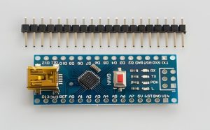
IC Programming and PCB Assembly
IC programming is closely connected to PCB assembly.
The production sequence can vary according to the product.
Option 1: Program Before Assembly
IC → Programming → Verification → PCB Assembly → Functional Test
Option 2: Program After Assembly
PCB Assembly → Programming Through Test Fixture → Verification → Functional Test
The second approach is particularly useful when firmware needs to be loaded into the completed product or when programming must be combined with final functional testing.
IC Programming Services
A professional IC Programming Services workflow can include several related activities.
Programming
The supplier loads the approved firmware or configuration data into the target IC using compatible programming equipment.
Serialization
Unique product information can be written to the device when required.
Examples include:
- Serial numbers
- MAC addresses
- Product IDs
- Calibration information
- Customer-specific parameters
Verification
The programmed device is checked to confirm that the expected data has been successfully loaded.
Marking and Traceability
Programmed devices may be identified through labels, barcodes, QR codes, lot numbers, or electronic production records.
This helps connect the programmed component with the relevant firmware version and production batch.
3D Inspection and Programming Quality
3D inspection and IC programming are separate manufacturing processes.
3D inspection systems can evaluate physical characteristics such as component height, coplanarity, solder paste volume, or component placement, depending on the equipment.
They do not replace firmware verification.
When a programmable IC is assembled onto a PCB, programming verification should be performed through an appropriate electrical or software-based method.
Common IC Programming Problems
| Problem | Possible Cause | Recommended Action |
|---|---|---|
| Programming failure | Incorrect device selection | Confirm IC part number and programming algorithm |
| Communication failure | Incorrect wiring or interface | Check JTAG, SWD, UART, SPI, or other connections |
| Verification failure | Corrupted or incorrect programming data | Check file integrity and repeat programming |
| Wrong firmware | Incorrect file revision | Implement controlled firmware release management |
| Device not detected | Power or signal problem | Check target voltage, ground, clock, and interface signals |
| Intermittent programming | Poor socket or pogo-pin contact | Clean and inspect contacts and fixture |
| Duplicate serial number | Poor serialization control | Integrate programming with traceability software |
| Board fails after programming | Hardware, firmware, or configuration issue | Perform functional and electrical troubleshooting |
Guidelines for Reliable IC Programming
Several design and production practices can improve programming reliability.
Add Programming Test Points
When in-system programming is required, designers should reserve suitable test points for the programming interface.
For example, JTAG or SWD signals can be routed to accessible test points or pogo-pin interfaces.
Consider Programming During PCB Design
Programming access should be considered during PCB layout rather than added after the board has been completed.
Important considerations include:
- Probe accessibility
- Connector location
- Signal integrity
- Ground reference
- Fixture clearance
- Board edge clearance
- Test-point size
- Manufacturing panelization
Control Firmware Versions
Firmware files should have clear revision control and release status.
Only approved production files should be used for manufacturing.
Verify the First Article
Before mass production, the programming process should be validated using representative boards or components.
The first programmed units should undergo appropriate verification and functional testing.
Maintain Suitable Adapters
IC packages vary considerably. Programming sockets and adapters should match the exact package and device family.
Examples include QFP, QFN, BGA, LGA, SOIC, DIP, and other package types.
The package itself does not determine whether an IC is programmable; programming capability depends on the device architecture.
Protect Sensitive Devices
ESD protection, correct handling procedures, suitable storage, and controlled programming environments are important for sensitive electronic components.
Benefits of IC Programming Services
Using a dedicated programming process can provide several manufacturing benefits.
Improved Production Efficiency
Automated or semi-automated programming systems can reduce repetitive manual operations and improve throughput.
Reduced Programming Errors
Controlled software, device identification, verification, and traceability can reduce the risk of loading incorrect firmware.
Better Traceability
Production records can associate firmware versions, serial numbers, device IDs, and test results with individual products or production lots.
Flexible Production
The same PCB hardware may support different firmware versions or customer configurations when the production process is designed accordingly.
Easier Functional Testing
When programming is integrated with PCB assembly and functional testing, manufacturers can verify both the programmed device and the complete electronic system.

Kingda IC Programming Support
Kingda can integrate IC Programming into PCB assembly and production testing according to the requirements of the project.
The programming process can be planned around the target device, firmware format, programming interface, PCB design, production volume, and traceability requirements.
Depending on the application, the manufacturing workflow may include:
- Firmware file preparation and verification
- Off-board IC programming
- In-system programming
- JTAG or SWD programming
- Microcontroller programming
- FPGA configuration
- Flash memory programming
- Serialization
- Programming verification
- Test fixture integration
- Functional testing
- Production traceability
For products requiring frequent firmware revisions, programming and testing procedures should be version-controlled so that the correct software is consistently matched with the appropriate PCB revision.
Conclusion
IC Programming is an important manufacturing process for programmable electronic devices. It enables microcontrollers, FPGAs, CPLDs, memory devices, processors, and other programmable ICs to receive the firmware or configuration data required for their intended applications.
The programming process can take place before or after PCB assembly. Off-board programming is useful when components need to be programmed before placement, while in-system programming provides a practical way to program devices after they have been installed on the PCB.
Reliable production requires more than simply loading a file. Device identification, firmware control, programming interfaces, fixture design, verification, serialization, ESD protection, and functional testing all contribute to a controlled manufacturing process.
By integrating IC Programming, PCB Assembly, and final testing into a coordinated production workflow, manufacturers can improve programming consistency, strengthen traceability, and reduce the risk of incorrect firmware or configuration data entering finished products.