
ICT Fixture Wiring: Keeping Resistance and Crosstalk in Check
An in-circuit test measures small quantities: a few milliohms on a power path, a few picofarads between two nets, a few microvolts of leakage. The probe is usually blamed first when a measurement drifts, and in a well-built ICT fixture the wiring is at least as likely to be responsible. None of those quantities tolerates a long and uncontrolled path between the instrument and the board.
Wiring inside a fixture is long, it is bundled, and it is routed close to other wires that carry switching transients. Each of those properties has a measurable effect, and all three can be controlled while the fixture build is planned rather than discovered during production.
Why Wiring Matters
The fixture is part of the measurement circuit. Every wire from the pin to the instrument adds resistance and inductance, and every wire running beside another couples a fraction of its signal into it. The instrument is calibrated at its own terminals while the measurement is taken at the board, so everything between the two belongs to the result. A fixture is therefore a circuit in its own right, and it deserves the attention given to the board it tests.
That is why a fixture built to the same schematic can perform differently from its predecessor. The topology is identical, and the lengths, the bundling and the ground returns are not, which is exactly why one fixture is stable and the other is intermittent.
The Resistance Budget
The budget starts from the tolerance of the test and works backwards. If a continuity test has to resolve twenty milliohms, then the wiring resistance, the probe, the connector and the return path together must consume a small fraction of that, or the margin is spent before the board is measured. The same arithmetic applies to capacitance and to timing, with different units and the same logic.
Writing the budget down is what makes it usable. A fixture with an allocation for each element can be reviewed when a new instrument or a longer cable is proposed, while a fixture without one is reviewed by testing, which is slower and happens later. The budget is also the document that makes one fixture comparable with the next one built for the same product.
Wire Gauge, Length and Routing
Gauge and length set the resistance of a channel, and routing sets its inductance. Short and thick is the general rule, and practical constraints turn it into a compromise, because a bundle has to fit the enclosure and the wires have to reach the pins without strain.
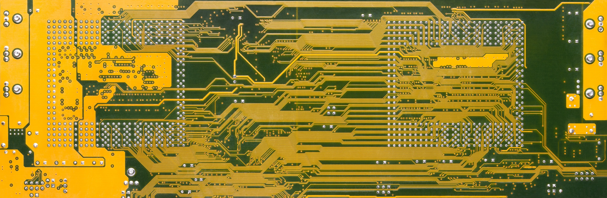
Where the compromise is unavoidable it should be made deliberately and recorded. Channels measuring the same kind of net should have similar lengths so that their errors are similar, because a systematic difference between channels is harder to compensate than a common offset.
Crosstalk Between Channels
The fixture switches channels one at a time, and the switching transients are fast. A wire carrying a step couples into its neighbours through capacitance and mutual inductance, and the coupled signal arrives at the instrument input as a small error or as a false edge. The error grows with the rate of change of the switched signal, which is why fast switching is harder to contain than slow switching.
Twisted pairs, shielded wires and separated bundles all reduce that coupling. The most effective measure is a return path running with the signal wire, because a signal that travels out and back along the same route encloses a much smaller loop area and therefore couples less into its neighbours.
Grounding and Reference
The ground of a fixture is not a single point. The resistance of the ground path is part of every measurement, and a shared ground carrying the current of several channels develops a voltage drop that appears as an error in all of them. Every measurement is taken between two points that are not at the potential of the instrument ground, and the difference adds to the reading.
Separating the measurement return from the switching return is the usual answer. The two are joined at one defined point, and the measurement currents are kept out of the path the switching currents use, so a channel being switched cannot disturb a channel being measured.
Connectors, Crimps and Intermittency
The connector at the fixture interface is where most intermittent faults begin. A crimp made with the wrong tool, a contact that has been repointed and a pin mated and unmated beyond its rating all produce a resistance that changes with temperature and with mechanical disturbance. The symptom is a test that passes, fails and passes again inside the same batch.
Intermittency is the hardest fault to find, because the fixture passes on the bench and fails on the line. Pull testing every crimp at the fixture build, and recording a torque or a mate count for the interface, moves the fault into the build instead of a production run.
Build Verification
Verification uses a golden board and a set of resistance measurements taken through the fixture. Each channel is measured from the instrument terminal to a known point, and the results are compared with the budget rather than with each other alone. The comparison shows which channels fall outside the allowance and by how much.

A four-wire measurement separates the wiring resistance from the contact resistance, which helps when a channel is out of budget and the cause has to be found. The verification record is kept with the fixture, and the notes on probe selection describe the other half of the same measurement path.
Maintenance and Repair
Repairs are frequent on a fixture with several thousand channels. A wire replaced with a longer one, a contact replaced with a different type and a bundle moved to make room all change the electrical behaviour of a channel, and each should return that channel to verification.
A repair log kept with the fixture makes the pattern visible. A channel repaired three times in a year has a mechanical problem, and replacing the wire again is a temporary answer. The interface between wiring and probe is covered in the notes on test point design.
Change Control and Records
A fixture is a measurement instrument and should be controlled as one. The revision of the wiring list, the date of the last verification and the result of that verification are the three fields that allow a change in test results to be attributed to the fixture or excluded from it. A fixture without a revision number cannot be shown to be the fixture that produced an earlier result.
Change control also covers the document that the test program uses. Where the fixture revision and the program revision are recorded together, a mismatch is visible before a batch is tested. The alternative to a fixture on some products is described in the notes on flying probe testing.
FAQ
Does wire length really affect a test? For resistance and timing measurements it does. The effect grows as the tolerance shrinks, and it is smallest on continuity checks with generous limits.
Can crosstalk be eliminated? It can be reduced below the resolution of the measurement. Twisted pairs and a return path beside each signal are the most effective measures.
Should every repair be reverified? Yes, at least on the repaired channel. A wire replaced with a different length changes that channel even when the connection is sound.