IMC Growth: 6 Rules for Solder Joint Life
IMC growth is the thickening of the intermetallic compound layer that forms where solder meets copper or nickel, and it begins in every solder joint from the moment the alloy melts. A thin layer is what makes the solder joint possible, because it is the chemical bond between the two metals, and without it there is no electrical or mechanical connection at all. A thick one is a liability.
The process cannot prevent IMC growth, and anyone claiming otherwise is describing a different phenomenon. What a process can do is limit how much growth happens during assembly, so that the joint starts its service life with margin rather than with a layer already at the limit.
What the Intermetallic Layer Is
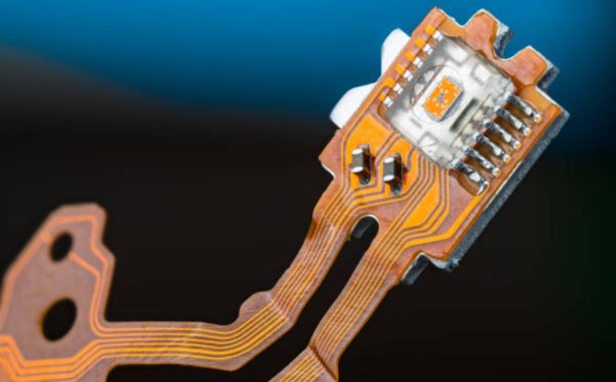
When molten solder contacts copper, atoms from each side diffuse into the other and form a compound with its own crystal structure, typically Cu6Sn5 next to the solder and Cu3Sn next to the copper. The layer is thin, hard and brittle compared with the solder around it.
The same process occurs over nickel and over the finishes used on pads, each producing its own compound. The chemistry differs from finish to finish, but the consequence for the solder joint is the same: a hard layer grows at the interface, and the solderability of the surface decides how uniformly it forms.
How IMC Growth Depends on Time and Temperature
The thickness usually follows a square root relationship with time, which means growth is fast at first and slows down. Temperature dominates: a modest rise in the joint temperature during service multiplies the rate, so a component running warm ages its solder joints far faster than one operating at room temperature.
That is why IMC growth is described as a thermal aging effect in reliability work, and why the same joint can be acceptable in one application and marginal in another where the ambient temperature is twenty degrees higher. The electrical load matters as much as the ambient, because self heating raises the joint temperature above the surrounding air. The thermal cycling data for a product is only meaningful when the temperature range is known.
Why a Thin Layer Is Necessary and a Thick One Is Not
A solder joint needs a continuous intermetallic layer to bond, and a joint with none is a cold joint that never formed properly in the first place. Once the layer is continuous, extra thickness adds no strength and only adds brittleness.
The risk appears when the layer occupies a significant fraction of the joint, because the remaining solder has less capacity to accommodate strain. A joint that was ductile at assembly becomes a hard, crack prone interface after years at temperature.
Copper Dissolution and Finish Selection
Copper dissolves into molten solder during soldering, and the amount depends on temperature, time and the volume of solder available. Thin traces under a small joint can lose enough copper to affect the joint, and the finish on the pad changes the rate at which it happens.
Nickel barriers slow the process considerably, which is one reason ENIG and similar finishes are used on fine geometry. Where gold is present, the gold embrittlement risk sits alongside the intermetallic question, because both are driven by the same temperature and time exposure.

Profile Choices That Limit Growth
The peak temperature and the time above liquidus are the two variables that matter most for IMC growth, and both are set by the reflow profile rather than by the solder alloy alone. A profile that reaches the minimum peak that produces sound joints generates less IMC growth than one that runs 20 degrees hotter for comfort.
Preheat, soak and cooling also contribute, though less directly. The practical rule is to qualify the profile to the lowest energy input that gives the required joint quality, then to hold it there in production rather than letting it drift upward.
Second Reflow, Rework and Cumulative Exposure
A double sided assembly passes through the oven twice, so the solder joints made on the first pass see a second thermal excursion before the assembly is complete. Rework adds another, and a board that has been touched up several times has joints with a history that no single profile describes.
That history is what makes IMC growth a cumulative problem, and it is the reason rework limits belong in the process documentation. Where a board is baked before assembly, that exposure also counts, and the baking schedule should be recorded with the same care as a reflow profile.
Measuring Intermetallic Thickness
Thickness is measured on a microsection at high magnification, with the section taken through the centre of the joint and prepared carefully so that polishing does not smear the soft layers together. Several measurements around the interface are averaged, because the layer is rarely uniform across the whole joint. The measurement is reported in microns and compared against a limit set by the application.
Because the layer is thin and the measurement is at the edge of optical resolution, the uncertainty has to be established before limits are set. Etching and image analysis improve the contrast, and the same preparation discipline used for other quality sections applies.
Failure Modes: Embrittlement and Kirkendall Voids
Two failures follow from a layer that has grown too far. The first is brittle fracture, where a crack runs along the intermetallic interface under mechanical or thermal shock. The second is voiding, where unequal diffusion rates leave small voids at the copper side of the layer.
Both are found after the fact by sectioning a failed joint, and both are prevented by controlling the exposure during assembly. Where a product runs hot in service, the same measurement taken on a field return is what closes the loop on the process window.
Specifying, Recording and Qualifying
The specification should state the finish, the solder alloy, the maximum peak temperature and the number of thermal excursions permitted, including rework. Those four values describe the exposure that a joint will see, and they are what a reliability prediction is built on.
Records should tie the profile, the rework count and any bake to the board serial number, so that a joint measured later can be matched with its exposure. Where a customer requires a thermal aging qualification, the test conditions and the acceptance criteria come from the IPC and JEDEC documents named in the specification.
FAQ
Can IMC growth be stopped completely? No. A joint without an intermetallic layer is not a joint, so the aim is to keep the layer thin and uniform rather than to eliminate it. Process control limits growth during assembly; the service temperature decides what happens afterwards.
Does a higher peak temperature make a stronger joint? Only up to the point where the joint is fully formed. Beyond that, extra heat thickens the intermetallic layer and consumes copper, which reduces the ductility that lets the solder joint survive thermal cycling in service.
How many reflow passes are acceptable? The limit comes from the product specification and from the qualification testing behind it, and it counts every excursion including rework and bake. Where no limit is stated, three passes is a common working assumption, not a guarantee.