
Length Matching and Timing Skew Control in PCB Routing
Two signals that leave a driver at the same instant must arrive at the receiver within a defined window of each other, or the interface will read the wrong data. Length matching is the practice of adjusting trace lengths so that the propagation delays line up, and it is one of the few layout tasks where a small geometric error has a direct timing consequence.
Why Trace Length Matters
Signals travel along a trace at a finite speed, typically around half the speed of light in a practical dielectric. A difference of a few centimetres between two parallel bus lines therefore translates into a delay difference of a few hundred picoseconds, which is comparable with the setup and hold window of a fast interface.
Length matching equalises those delays. It is applied to groups of signals that must arrive together, such as a data bus and its strobe, or the lanes of a serial link. The requirement comes from the interface specification, not from a general preference for neat routing, and it is normally expressed as a tolerance within the group, such as matching to within a stated length.
Propagation Delay and Velocity
The propagation delay of a trace depends on its length and on the effective dielectric constant of the material around it. A trace on an inner layer is surrounded by laminate and is slower than a trace on the surface, where part of the field is in air. The difference is significant enough that mixing layers within a matched group is a real source of skew.
The delay also depends on the geometry, because a wide trace and a narrow one see slightly different effective dielectric constants. The effect is small but measurable, and it matters most when a group mixes widths deliberately, such as a clock routed wider than its data lines.
<img src="https://www.gopcba.com/wp-content/uploads/2026/09/232-1.jpg" alt="Serpentine length tuning added to traces of a matched bus group” />
Skew Budgets and Timing Margins
The skew budget is the portion of the timing margin allocated to length mismatch. It is derived from the interface timing specification, the clock and data relationship, the receiver’s setup and hold requirements and the other contributors such as driver skew and package delay.
Once the budget is known, it converts to a length allowance using the propagation velocity. A budget of fifty picoseconds corresponds to a length difference of about eight millimetres in a typical dielectric, which is a useful figure to keep in mind when routing a group into a connector.
Matching Groups and Interfaces
Matching is applied within a group, not across the whole board. A memory bus is one group, a display interface is another, and the two do not need to match each other. Within a group, the specification usually defines a reference signal, and every other member is matched to it.
Some interfaces match all members to each other, while others match to a clock or a strobe that has its own defined relationship. Reading the requirement correctly matters, because matching to the wrong reference produces a build that satisfies the layout rule and still fails timing.
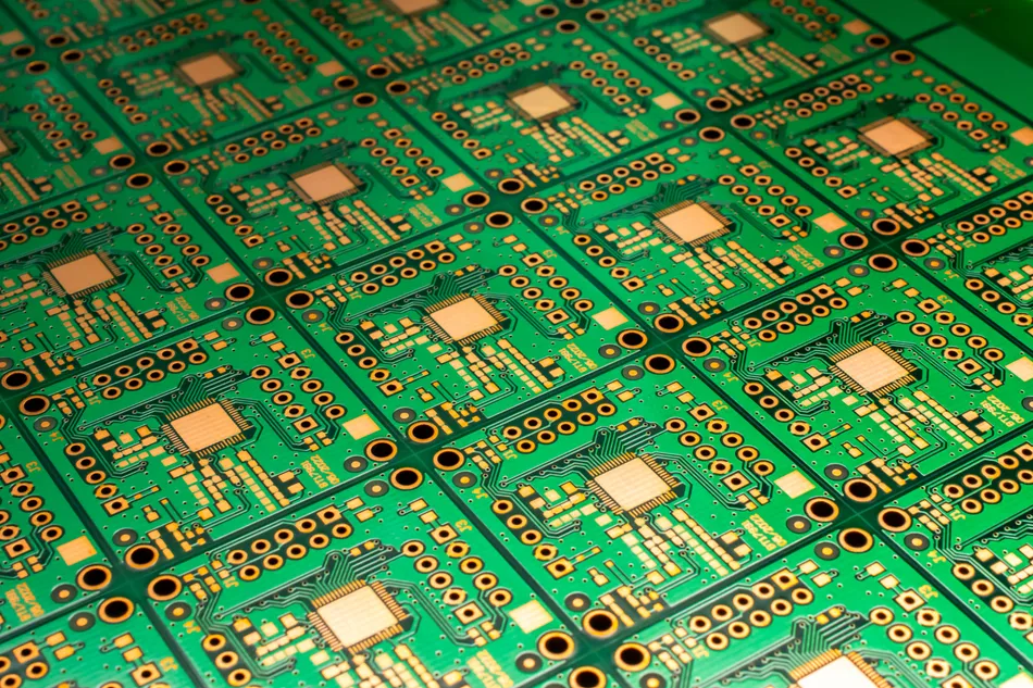
Serpentine Tuning Done Properly
The usual method of adding length is a serpentine, a zigzag section that increases the path without changing the endpoints. The amplitude and pitch of the serpentine determine how much it disturbs the line: a tight, compact serpentine adds capacitance and can create its own impedance discontinuity and crosstalk.
Good practice is to keep the serpentine amplitude at least a few times the trace width and the pitch large enough to avoid coupling between adjacent segments. Serpentine should be placed where the mismatch occurs rather than at the end, and it should be kept away from other sensitive nets. Where a large amount of length has to be added, it is better to absorb part of it by routing a longer path in the first place than to build a dense serpentine into a small area.
Layer and Via Effects
Layer changes introduce delay of their own. A via adds a small amount of length equivalent, and two traces of equal physical length on different layers are not equal in delay. Where a group must change layers, the change should be applied to all members in the same way so that the mismatch is common.
Via stubs also affect the signal beyond the delay: a stub creates a resonance that degrades the waveform at high frequency. Avoiding stub effects is one reason for back drilling in thick high speed boards, and the practice is described in this guide to high speed design rules.
Material and Weave Effects
Glass weave in the laminate makes the effective dielectric constant slightly different depending on the direction a trace runs relative to the weave. Two traces of identical length can therefore have different delays if one runs along the weave and the other across it, which is a source of skew that layout cannot fix by adding length.
The practical responses are to route matched groups at a consistent angle, to use spread glass or a filled laminate, or to accept the variation and allocate it within the budget. The material properties involved are described in this guide to laminate material properties.
Measuring and Verifying
Verification begins with the layout tool, which can report the length of each member of a group against the target. That check is necessary but not sufficient, because it works in physical length rather than delay and it cannot account for layer or material effects.
Time domain measurement on a coupon confirms the actual delay of the production geometry. A coupon with traces of defined length on each layer gives the delay per unit length that the design assumed, and it exposes any difference between the calculation and the built board. The coupon approach is described in this guide to test coupons.
Documentation and Review
The matching requirement belongs in the design documentation with the group definitions, the reference signal, the tolerance and the delay per unit length that was assumed. Without those, a later revision cannot tell whether the matching was satisfied or what the constraint actually was.
The requirement should also be visible to the fabricator, because some of the contributors, such as layer assignment and dielectric thickness, are under their control. Where the design depends on a particular construction, that dependency should be stated rather than inferred, and the layer arrangement is described in this guide to layer assignment rules.
Related reading: our fabrication notes, board quality and design release notes cover the same ground.
FAQ
How tight does length matching need to be? It depends on the interface and the rise time, and the number should come from the timing budget rather than from a rule of thumb. Common values range from a small fraction of the bit period for source synchronous buses to a few hundred micrometres for very fast serial links.
Does a longer trace always mean a longer delay? Longer is slower on the same layer with the same geometry, but a shorter trace on an inner layer can have a longer delay than a longer one on the surface. The comparison only holds when the layer, width and material are the same.
Should every signal on a bus be matched? Only the members of the group defined by the interface, and only to the reference the specification names. Matching unrelated nets to each other adds routing difficulty and consumes area without improving the timing of anything that matters.