Mounting Hole: Mechanical Constraints That Shape the PCB Layout
A printed circuit board is a mechanical component as much as an electrical one, and the mechanical requirements are usually stated late, after the layout is under way. Bringing them forward removes most of the late redesign that mechanical constraints otherwise cause.
What the Mechanical Interface Fixes
The enclosure, the mounting points, the connectors and the height limit together determine the outline, the position of every connector and the maximum height of every component. Those constraints are not negotiable by the electrical design.
The consequence is that the placement should begin with the mechanical features and build the electrical function around them, rather than placing the electrical function and then moving parts to fit. Our board outline notes describe how the outline is specified.
Mounting and Fastening
Mounting holes are the points through which the board is fixed, and their position determines how the board vibrates and how the stress is distributed. A board supported at two points flexes more than one supported at four.
The fastening method also matters. A screw with a metal insert transfers clamping force into the laminate, while a plastic standoff provides compliance. The choice is made for the environment, and it affects the keep-out around each hole. Our fastening notes describe the options.

Component Height and the Enclosure
The height limit is set by the enclosure and is usually tighter than the designer assumes, because the limit applies to the assembled board including the solder joint and any coating. A tall capacitor that fits on the drawing may not fit under the lid.
The safe approach is to record the height of every component on the assembly drawing and to compare the maximum against the enclosure’s internal clearance, allowing for tolerances on both.
Connector Access and Cable Routing
A connector that cannot be reached with its mating plug is unusable, and the space needed for the plug is often larger than the space needed for the connector. Cable routing imposes a minimum bend radius that also consumes space.
Those requirements are mechanical rather than electrical, and they belong on the outline drawing so that the placement can respect them. Discovering them at the enclosure stage produces a redesign of the board and of the housing at the same time.
Handling and Assembly Features
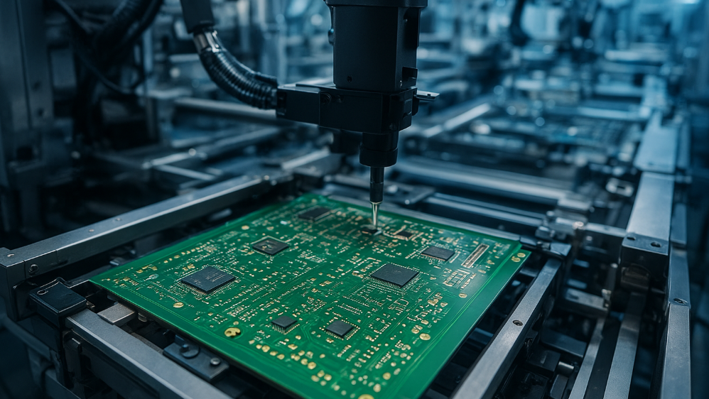
A board is handled many times during assembly, and providing places to grip reduces the risk of damage to components. Tooling holes, a clear border and a defined breakaway region all serve that purpose.
The same consideration applies to service. A board that has to be removed from its housing should allow the removal without disturbing the cables, which usually means the connectors face the same direction.
Marking and Identification on the Finished Product
The finished product needs an identifier that can be read without disassembly, which places a requirement on the marking position as well as on its content. A code that is hidden by a connector or a cable is not a usable identifier.
The position should be chosen with the assembled product in mind, and it should be accessible enough that a service technician can read or photograph it in place. Our traceability marking notes describe the encoding options.
Vibration and Shock Requirements
Where the product will be subjected to vibration, the mechanical design determines which components are at risk. A heavy component mounted on a large unsupported area of board will flex the board and stress its own joints.
The remedies are additional mounting points, a local stiffener, a change in the board thickness or, where none of those is possible, an adhesive that holds the component against the board.
Thermal Expansion and Mechanical Stress
As the board warms, it expands, and the enclosure expands by a different amount if it is made from a different material. The mounting points are where the difference is absorbed, and a design that constrains the board too rigidly converts the difference into stress on the board or on the housing.
Providing some compliance, either in the mounting or in the fastener, avoids the problem. The alternative of matching the materials is usually not available.
Getting the Mechanical Data Early
The single most useful action is to obtain the enclosure drawing, or at least the internal dimensions and the mounting positions, before the placement begins. The cost of a short mechanical review at the start is small compared with the cost of moving connectors after the routing is complete.
Where the enclosure does not exist yet, a mechanical envelope can be drawn and agreed. It is a simpler artefact than a housing model and it captures the constraints that matter. Our design review notes describe where it belongs in the flow.
Process Control and Verification
On a design of this kind, stiffener is the item that decides how the rest of the board is arranged. Documenting the assumption is part of the design work, and a short note on the drawing prevents a question that would otherwise arrive a day later and cost a day of schedule. The process window is set by the narrowest step in the flow, so an improvement anywhere else shows up as margin rather than as yield until that step is addressed.
A short note on the drawing about handling, storage or packaging is often worth more than an extra decimal place on a tolerance. Where a value sits close to a process limit, the drawing should say so, since the shop can then open the process window rather than working to a nominal figure that carries no tolerance.
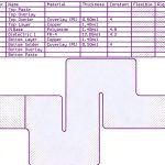
A stack-up that is drawn rather than described removes most of the ambiguity from a quotation, and it lets the fabricator price the board against the dielectric and copper weights that will actually be used.
Process Control and Verification
On a design of this kind, stiffener is the item that decides how the rest of the board is arranged. Documenting the assumption is part of the design work, and a short note on the drawing prevents a question that would otherwise arrive a day later and cost a day of schedule. The process window is set by the narrowest step in the flow, so an improvement anywhere else shows up as margin rather than as yield until that step is addressed.
Process Control and Verification
On a design of this kind, stiffener is the item that decides how the rest of the board is arranged. Documenting the assumption is part of the design work, and a short note on the drawing prevents a question that would otherwise arrive a day later and cost a day of schedule. The process window is set by the narrowest step in the flow, so an improvement anywhere else shows up as margin rather than as yield until that step is addressed.
FAQ
How many mounting holes does a board need? Enough that the span between supports does not resonate at a frequency the environment excites, and enough that the board sits flat. A large board with two holes is a board that will flex, whatever its thickness.
Does a mechanical constraint ever justify a worse layout? It does, because the product has to fit its housing. The judgement is about which electrical compromise costs least, and that judgement is better made early when the alternatives are still open.
What does gopcb need to confirm the mechanical design? We need the outline with tolerances, the hole positions and diameters, the maximum component height, the panel arrangement and the position of any feature that must not be coated or marked. Confirming those before the panel is released avoids a rework of the tooling.