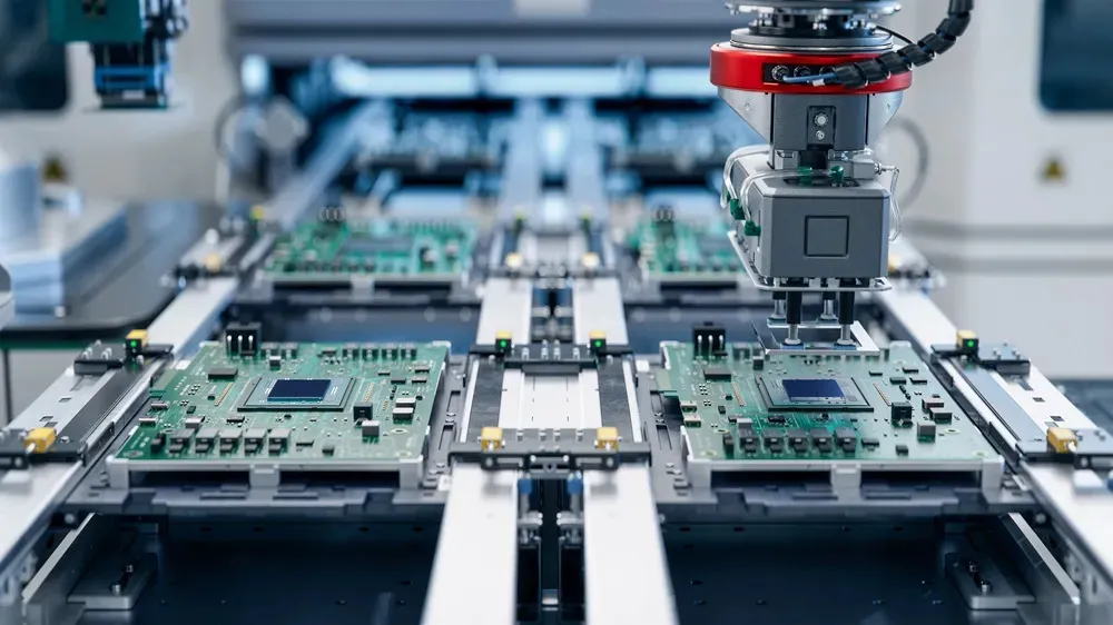
Medical Electronics PCB: Applications and Requirements
Medical electronics is a broad category that ranges from a disposable glucose strip to a surgical robot, and the boards inside them have little in common except the regulatory framework they sit in. What distinguishes a medical PCB is not usually the circuit but the consequences of its failure, and that changes the design, the materials, the testing and the documentation. A board that is adequate for a consumer product can be entirely unacceptable in a device that delivers therapy to a patient.
The Categories and What They Require
The requirements scale with the risk. A monitoring device that informs a clinician has different expectations from one that makes a decision, and a device that delivers energy to a patient is different again. The classification determines the design controls, the verification and validation effort, the clinical evidence required and the process controls imposed on the manufacturer.
That classification propagates down to the board. A Class 3 acceptance class is common, materials are selected from qualified lists, and every change to the design, the material or the process is documented and assessed. Where the device is implanted or disposable, additional requirements appear: biocompatibility, sterilisation compatibility, and a shelf life that the packaging and the electronics both have to survive.
Isolation and Patient Safety
Wherever a patient is connected to the electronics, isolation is the central design requirement. Even a battery powered device can present a hazard if it is connected to a mains powered instrument while a patient is in contact with it, and the standard approach is to provide a barrier between the patient connected circuitry and everything else. The applied part, which is the part of the device that touches the patient, has its own classification and its own isolation requirement.
Physically the barrier is realised exactly as it is in any isolated design: creepage and clearance distances that satisfy the standard, a continuous barrier across the board, and isolated devices straddling it. What differs is the rigour with which it is verified, since the barrier is tested on every unit and the test result is recorded. Our design release checklist covers the documentation that accompanies those tests.

Leakage, Defibrillation and Other Transients
Patient connected circuits have to limit the leakage current that can flow through the patient, which constrains the capacitance that may be connected to the applied part and the filtering that may be used on patient connected lines. A filter that would be entirely reasonable elsewhere may be unacceptable because its capacitors provide a path for leakage current, and the design has to achieve its noise performance without them.
Defibrillation protection is the other requirement that has no equivalent in other products. A patient connected device may be attached when a defibrillator is discharged, and the resulting energy has to be absorbed without damage and without presenting a hazard. That means series impedance, energy absorbing devices and a layout that routes the energy away from the sensitive circuitry, and it means the protection components are tested rather than assumed.

Materials, Cleaning and Sterilisation
A board that will be sterilised has to survive the process, and the process may be steam, hydrogen peroxide, ethylene oxide or radiation. Each attacks materials differently, and the choice of laminate, solder mask, coating and connector is driven by the sterilisation method rather than by the electrical requirement. Where the device is single use, the board may also have to survive the shelf life of the packaged product without its surface finish degrading.
Cleanliness matters for a different reason. Ionic contamination left by the assembly process can cause leakage or corrosion, and on a patient connected circuit that leakage is a safety issue rather than a performance one. The cleaning process is therefore specified, controlled and verified, and residue testing is part of the acceptance criteria rather than an optional check.
Reliability and Failure Modes
The design assumes that a component will fail, and it is arranged so that the failure is safe and detectable. A monitoring channel that fails should not report a normal reading, a therapy delivery path that fails should not deliver energy when it should not, and a display that fails should be obvious. That reasoning determines which signals are monitored, which redundancies are provided and how the device behaves at its limits.
Reliability is also demonstrated statistically. Accelerated life testing, thermal cycling, humidity and, for implantable devices, extended soak testing produce data that is used to predict the failure rate over the intended life. Where the prediction is uncertain, the design margins are widened rather than the claim being softened, because the consequences of being wrong are not commercial.
Production and Traceability
The manufacturing process is part of the regulated product. Every board is traceable to the panel it was cut from, the process parameters used to build it and the inspection results it produced, and the records are retained for a period specified by the standard. Changes to the process are documented and assessed, and a change of supplier for any critical material is a change to the product.
Testing reflects the same discipline. Functional test is performed on every unit, often at temperature, and where a device cannot be fully tested without being operated, the test includes a mode that exercises the hardware beyond its normal operating range. Designing the board so that this is possible, with test points and accessible interfaces, is part of the design rather than an addition to it.
Diagnostics, Service and Software
A medical device is serviced in the field, and the board has to make that possible. Diagnostic self-tests that verify the signal chain without requiring a patient, error codes that identify which subsystem failed, and a service interface that is separate from the user interface are all common requirements. They are board design decisions as much as firmware ones, because they need test points, reference measurements and isolated access.
Where the device contains software, the development process is regulated alongside the hardware. That means the interfaces between the two are specified, the hardware behaviour under fault conditions is defined rather than emergent, and a firmware update follows the same change control as a hardware revision. Designing the board with a defined boot behaviour, a watchdog and a safe state that it can reach on its own makes that regulation much easier to satisfy. Our component tolerance and reliability notes describe how those fault states are assessed.
Where Medical Boards Are Used
The range of applications is wider than it first appears. Diagnostic imaging needs high speed acquisition with low noise. Patient monitoring needs isolated front ends with very low leakage. Infusion and therapy delivery needs motor control with a monitored output. Laboratory instruments need precision measurement and repeatability. Portable and wearable devices add battery life, miniaturisation and wireless communication to the same requirements.
What they share is the consequence of failure, and that is what makes the design effort proportionate to the risk rather than to the complexity. A simple board that measures a temperature and transmits it may carry more design control than a much more complicated board in an industrial product, because of what happens if the number is wrong. Our design release checklist places those considerations in the sequence.
FAQ
Why is a Class 3 acceptance class common in medical electronics? Because the equipment must function when it is needed, and a marginal joint that would be acceptable elsewhere is a risk that cannot be justified.
What is an applied part? It is the part of the device that comes into contact with the patient, and it carries its own classification and isolation requirements because it determines what current can reach the patient.
Why is cleaning so important? Because ionic residue from the assembly process provides a path for leakage current, and on a patient connected circuit that leakage is a safety issue rather than a performance one.