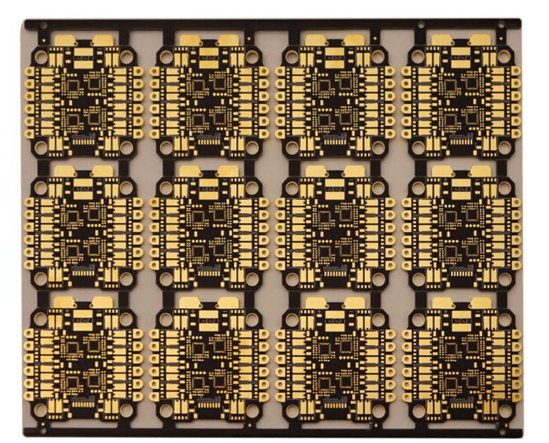
Medical PCB Manufacturing for Reliable Devices
Medical electronics need boards that hold their electrical behavior over years of use. A monitor, analyzer or surgical console may run every day in a clinic, so a small process drift becomes a field failure. This review sets out how medical PCB work is planned, built and checked, from the first engineering question to the last test record. It is written for engineers and buyers who must compare suppliers on evidence rather than on a headline price.
The scope covers fabrication, assembly and test for healthcare products. Multilayer, HDI, flexible and rigid-flex constructions all appear in this market, and each brings its own process risks. The aim here is to show where those risks sit and what a buyer should verify before release. A supplier that explains its controls clearly is easier to trust than one that only lists machines.
What Defines a Medical PCB
A medical PCB is a circuit board built for equipment used in diagnosis, monitoring, treatment or laboratory work. The board carries sensors, processors, power circuits, communication modules and displays, and it must connect them without degrading weak signals. Requirements vary widely between a handheld monitor and a benchtop analyzer, so no single specification covers the whole market. The device, its environment and its quality requirements set the real target.
Reliability matters more here than in consumer products. A board that fails in a clinic interrupts care and can cost far more than the part itself. Designers therefore pay attention to material stability, copper quality, solder joint integrity and surface finish. These choices interact, and a change in one place often shifts another. Reviewing them together at the start avoids surprises later in the build.
Stackup and Material Choices
Material selection starts with the electrical and thermal load the board must carry. Standard FR-4 suits many designs, while high-TG laminate helps where heat is constant. Flexible and rigid-flex materials allow three-dimensional assembly and reduce cable joints. High-frequency laminates serve imaging and sensing circuits that cannot tolerate loss. The right answer depends on signal speed, operating temperature and mechanical stress, not on a default preference.
Layer count and stackup follow the same logic. More layers help routing density and shielding, but they add lamination steps and cost. Controlled impedance requires a defined dielectric thickness and trace geometry that the fabricator can hold in production. Buyers should ask for the stackup drawing and confirm that the quoted build matches it. A stackup agreed in writing prevents arguments when the first panels arrive.
Moisture is a quiet material risk that deserves early attention. Laminates absorb water during storage and machining, and trapped moisture expands violently in reflow or lamination heat. The result can be blistering, delamination or a measured shift in dielectric constant. Suppliers should bake panels before heat cycles and store cut material in controlled humidity. Buyers can ask for bake records and storage conditions, because these details rarely appear on a quotation but decide yield.
Fabrication Process Control
Fabrication begins with an engineering review of Gerber data, drill files and the bill of materials. The review looks for trace spacing, drill sizes, annular rings and panel utilization that could cause trouble on the line. Inner-layer imaging and etching set the copper pattern, and lamination bonds the layers under heat and pressure. Registration between layers is checked because drift there breaks connections later.

Drilling follows lamination, and it carries real risk in dense medical boards. Small holes, high aspect ratios and via-in-pad structures demand sharp tools and stable machines. Plating must fill the barrel evenly, or a via becomes a weak point under thermal cycling. Surface finish then protects the copper and supports soldering. Each step is recorded, and that record is what lets a fabricator trace a defect back to its cause.
Copper plating thickness is a common failure point in high-aspect-ratio holes. Thin plating at the barrel center cracks under thermal cycling, and the fault may not appear until the board has run for months. Fabricators control this through current density, bath chemistry and agitation, then confirm it with cross-section coupons. Buyers should ask how plating thickness is verified and whether coupons are kept with the lot. A fabricator that measures rather than assumes is easier to hold to a specification.
Assembly and Solder Quality
Assembly turns a bare board into a working unit. Solder paste printing controls volume, placement sets position, and reflow forms the joints. Each stage feeds the next, so a paste problem shows up as a placement fault or an open joint. Medical boards often mix fine-pitch parts with connectors, which makes stencil design and profile choice important. SMT PCB assembly lines handle this mix when the process window is defined and monitored.
Through-hole and mixed-technology work still appears in medical equipment, especially around connectors and power parts. Those joints need enough heat without stressing nearby components. Cleaning matters too, because residue can affect performance in humid conditions. Buyers should confirm which assembly route applies and how the supplier controls it. A clear process sheet, signed at first article, gives both sides a reference for every later lot.
Component sourcing is part of assembly quality, not a separate purchasing task. Counterfeit or mislabeled parts defeat every process control downstream, so incoming inspection and approved alternates matter. Medical programs also face long life cycles, which means a part can go obsolete mid-production. Suppliers should flag end-of-life notices early and propose qualified replacements. Buyers should ask how alternates are approved and whether any change reaches the drawing before it reaches the line.
Inspection and Test Coverage
Inspection catches defects before they leave the factory, and its greater value is the feedback it gives. Optical inspection finds placement and solder faults, while X-ray reveals hidden joints under packages. Electrical test confirms connectivity and checks for shorts. Functional test then proves the board works as a system. PCBA testing should be planned around the failure modes that matter for the device, not applied as a fixed menu.
Test coverage has limits, and buyers should know where they sit. A board can pass electrical checks and still fail in the field if a joint is marginal or a component is out of tolerance. Reliability checks and burn-in add confidence for critical designs. The test plan should name the defect each step is meant to catch. That link between test and risk is what makes a program useful rather than decorative.
Prototype and Volume Transitions
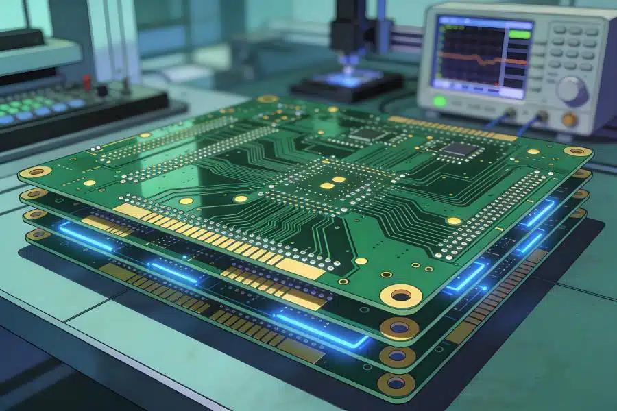
Most medical programs start small and grow. A pilot batch reveals pad geometry issues, component tolerances and process behavior before large orders are committed. rapid PCBA prototyping helps teams validate a design while the schedule still allows changes. The lessons from those early boards should feed back into the fabrication and assembly documents. Skipping this stage usually costs more later.
Moving to volume brings its own questions. Tooling, panel design and component supply must scale without changing the process that was qualified. A supplier that runs prototypes and production in one facility can keep the settings consistent. Buyers should ask how the transition is handled and who signs off the first production lot. A documented handover reduces the chance that a qualified design drifts once volumes rise.
Supplier Checks That Matter
Comparing suppliers on price alone hides the real cost of a weak process. Engineering support, material control, inspection data and delivery record all affect the total. A partner that reviews files before production and reports risks honestly is usually cheaper over a project than one that quotes low and surprises later. quality management should be visible in records, not only in a certificate on a wall.
Ask for the process sheet, the inspection plan and a sample test report. Confirm how changes are handled, who approves them and how the change reaches the next lot. Check that component sourcing includes incoming verification and approved alternates. These questions are simple, and the answers show whether the controls are real. A supplier that answers them clearly is easier to audit and easier to work with across repeat orders.
Traceability deserves its own question. A medical board should be linked to the panel it came from, the material lot, the paste batch and the test program that ran. When a field return arrives months later, that record is the fastest route to a cause. Buyers should ask how long records are kept and whether they can be retrieved by serial number. Suppliers that keep this data well usually keep their processes well too.
Integration is the final point to weigh. When fabrication and assembly sit under one roof, PCB assembly and bare board issues are resolved by one team rather than passed between vendors. That shortens the loop when a defect appears and keeps the drawing, process sheet and inspection plan aligned. For medical programs with long validation cycles, this continuity saves time and reduces risk. It also gives the buyer a single point of accountability from quotation to shipment.