Mixed Technology PCBA: Planning Through-Hole Insertion
A board that carries both surface mount and pin-in-hole components is assembled in two stages, and the second stage is where most of the scheduling difficulty lives. The mixed technology process places and reflows the surface mount devices first, then adds the parts that have to be inserted — relays, transformers, terminals, electrolytic capacitors and the larger connectors — and solders them without disturbing what has already been built.
Because the insertion stage happens after reflow, it has to be planned around the fact that the board is already populated. That constraint shapes the data that is needed, the way the parts are prepared, the choice of soldering method and the way the first article is checked.
Which Boards Need an Insertion Stage
The need is set by the components rather than by the product. Small passives and packaged devices belong with the placement machines; parts that carry mechanical load, dissipate significant heat or must be serviceable are usually through-hole. Many industrial control boards, power supplies, communications units and instrument assemblies contain both, and the quotation depends on the insertion data as much as on the placement data.
An enquiry that includes only a placement file and no insertion drawing cannot be costed accurately, because the number of inserted parts, their orientation, their height and any forming requirement are all part of the work. Supplying both sets of data with the assembly drawing is what allows the two stages to be scheduled as one flow.
The Data the Insertion Stage Requires
Fabrication data, the bill of materials, the placement file, the assembly drawing and the insertion drawing form the package. The insertion drawing carries the reference designators, the installation orientation, the side of the board and any special requirement. Horizontal mounting, stand-off height, a bend in the lead or a specified retained lead length are all instructions that have to be written down, because the operator cannot infer them from the board.
Components with a defined direction — electrolytic capacitors, diodes, relays and connectors — depend on the bill of materials and the silkscreen agreeing with each other. Where the two disagree, the drawing decides, and the discrepancy should be raised before the run rather than resolved at the bench.
Incoming Checks on Parts and Holes
Through-hole parts are inspected on arrival for part number, lead form, packaging and appearance. Oxidised, bent or dimensionally incorrect leads make both insertion and soldering unreliable, and a lead that has been straightened by hand is not the same as one that arrived straight.
The board is checked in the same pass. Hole diameter against lead diameter matters in both directions: a lead close to the upper limit of the hole can be difficult to insert without damaging the barrel, while an oversized hole affects how the solder fills. Component height and the space around it are confirmed against the drawing, because a tall part installed in the wrong orientation can interfere with the enclosure or with a module fitted later.
Choosing Between Hand, Wave and Selective Soldering
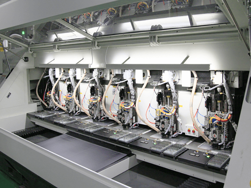
Three methods cover most insertion work. Hand soldering suits small quantities and scattered positions, where setting up a machine would cost more than the joints it produces. Wave soldering suits boards with many inserted parts arranged in a regular orientation, provided the surface mount devices already on the underside can tolerate the process or have been protected from it. Selective soldering suits boards where only defined areas may be heated, which is common when the underside carries components that the wave would damage or when the board is heavily populated on both sides.
The choice follows the quantity, the distribution of the parts, the structure of the board and the temperature limits of what is already on it. In every case the two variables that must be controlled are temperature and time: too little heat leaves an unsatisfactory joint, and too much dwell damages the component, the pad or a plastic connector body.
First Article and Continuous Assembly
The first inserted board is confirmed for part number, reference designator, orientation, height and joint condition, with particular attention to the capacitors, diodes, relays and connectors that will not tolerate a reversal. Once that board is accepted, the method it demonstrated is used for the rest of the batch.
During the run, the recurring risks are a part that floats above the board, a part that leans, and a part that is simply omitted. A fixture or a support that holds the component down while it is soldered removes the first two, and a checklist against the insertion drawing removes the third.
Inspection After Soldering
Inspection covers insufficient solder, bridging, disturbed joints, solder balls and lead length. Where leads have to be cut after soldering, the cut is made in a way that does not transfer stress into the joint, because a joint that has been pushed while it was solidifying is a joint that will fail later without showing anything at inspection.
<img src="https://www.gopcba.com/wp-content/uploads/2026/05/AI边缘算力盒子PCBA.png" alt="wave soldering of inserted through-hole components” />
Where the order includes lead forming, the forming is done before insertion with a tool that produces the same shape every time. Hand-bent leads vary from part to part, and the variation shows up as an inconsistent stand-off height that affects both the soldering and the fit into the enclosure.
Testing After Insertion
Appearance is not enough at this stage. Relays, terminals, transformers and connectors take part in the power path or the load path, and their behaviour is confirmed by testing rather than by looking at the joint. The test voltage, the connection method, the operating sequence and the acceptance values come from the customer, and where a fixture is supplied it is proved before the batch is scheduled.
The insertion operations are handled as through-hole assembly and mixed technology assembly, the surface mount stage as SMT assembly, the electrical verification as PCBA testing, and a finished unit that goes into its enclosure is delivered through box build assembly.
Scheduling the Two Stages Together
The surface mount stage and the insertion stage are usually planned as one flow, because a board that has been reflowed and then waits for parts is a board that occupies space, risks damage and may need to be cleaned again before it can be soldered. Where the inserted material is customer supplied, the second stage cannot start until it arrives, and the schedule for the whole order therefore depends on the slowest item rather than on the assembly time.
Keeping the two stages in the same programme also means the first article covers both. A board that was confirmed after reflow and then re-confirmed after insertion has been through two acceptance points, and any interaction between the processes — a component disturbed by handling, a mask that was damaged by the wave, a joint that moved while it cooled — is found before the batch is built rather than after it has shipped.
Cleaning, Handling and Packaging
Where the process leaves flux residue that the customer’s specification does not allow, the cleaning method is chosen so that it removes the residue without attacking the parts that were already assembled. A board that carries a plastic connector, a relay or an unsealed component has a limit on what can be washed and how, and that limit is part of the process decision rather than an afterthought.
Handling between the stages is controlled for the same reason: boards are supported rather than stacked, inserted parts are not used as handles, and the packaging at the end carries the load through the board rather than through the tallest component.
FAQ
Why does insertion need its own drawing? Because the technique of inserting a part, its orientation and its stand-off height are not all visible on the board, and the operator needs the instruction rather than the inference.
When is selective soldering preferred over wave soldering? When part of the board cannot be heated — typically because surface mount components on the underside would be damaged — or when only defined areas carry inserted parts.
Is a visual check of the joints sufficient? No. Parts in the power and load path are confirmed by functional test, and the acceptance values come from the customer’s specification.