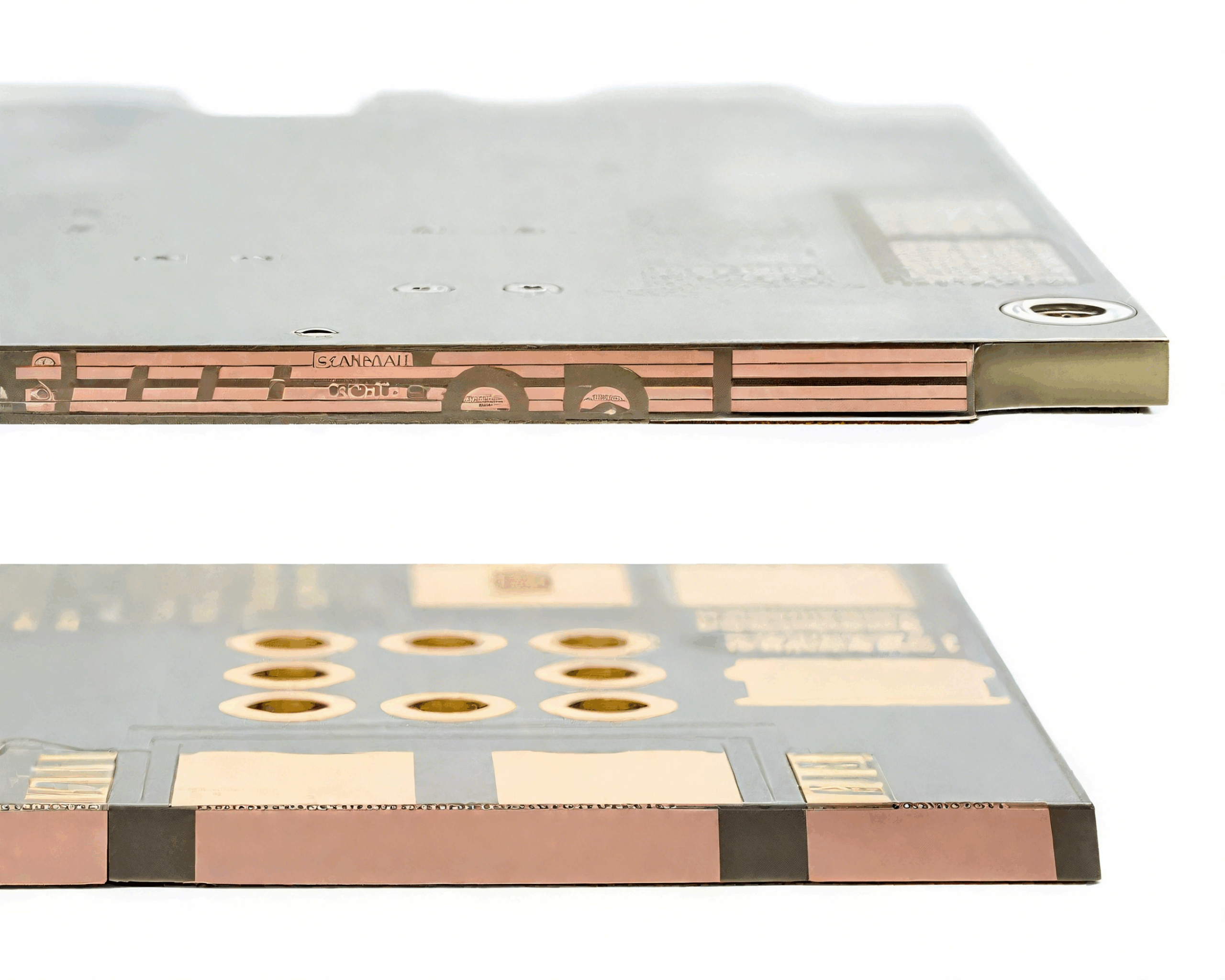
MOSFET Parallel Connection Circuit Design
Paralleling MOSFETs is the standard way to carry more current than a single device can handle, and it works well when the layout and the gate drive are symmetric. It fails when one device takes more than its share, and the failure is usually thermal rather than electrical.
Why Current Sharing Is Uneven
The on resistance of a MOSFET rises with temperature, which is the property that makes paralleling possible at all. A device that takes more current gets hotter, its resistance rises, and the current shifts to its neighbours.
The sharing is therefore stable at direct current, and the residual imbalance comes from the variation of the threshold voltage and the transconductance between devices. Parts from the same wafer lot differ by a few percent, and the current divides in roughly that proportion.
The transient sharing is a different matter. During switching the devices pass through the linear region where the current is set by the transconductance rather than by the resistance, and a device with a lower threshold voltage turns on first and takes the whole current for a few tens of nanoseconds.
Matching and Device Selection
Devices from the same production lot and the same date code match closely, and buying them together is the cheapest improvement available. A batch of parts from different suppliers mixed on one board is a reliability problem rather than a sourcing convenience.
The threshold voltage and the transconductance are the parameters that matter. The on resistance matters less than it appears, because the positive temperature coefficient corrects for it once the devices are hot.
Where the current is large, the devices are usually derated so that the combined rating is well above the operating current. A hundred percent derating, meaning two devices rated for the full current, is not necessary, but leaving no margin at all turns a small imbalance into a failure.

Gate Drive and gate resistor
Each device needs its own gate resistor, placed at its own gate. A single shared resistor lets the devices interact through the gate circuit, and the one that turns on first can pull the gate of the other through the shared inductance.
The gate resistors should be equal in value and the gate traces equal in length. The purpose is to slow the switching enough to keep the devices in step and to damp the oscillation that occurs between the gate inductance and the gate capacitance.
The drive current to the gates is the sum of the individual gate currents, and the driver has to supply it. A driver that is adequate for one device may be too slow for four, and the switching losses then rise in all of them at once.
parasitic oscillation
parasitic oscillation occurs between the gate inductance and the gate capacitance of a device, or between two devices through the shared source inductance. It appears as a high frequency burst on the gate waveform at the switching edge.
The cure is a gate resistor close to the device, a source connection with minimal shared inductance and, where needed, a ferrite bead on the gate. A long gate trace with a shared return is an oscillator waiting to happen.
Oscillation is more likely with several devices in parallel because the total gate capacitance is larger and the loop impedance is lower. Measuring the gate waveform of each device individually is the only way to see it, and the measurement needs a probe with a short ground lead.

Layout for Equal Current
The layout has to make the impedance from each device to the load identical. Symmetric placement about the centre of the current path, equal trace widths and equal lengths are the requirements, and a layout that looks tidy but is asymmetric defeats the purpose.
The source connections are the critical ones. The source inductance shared between devices carries the sum of the currents, and it appears in series with every gate circuit. A separate source connection for each device back to a common point removes the shared path.
Heat sinking is part of the symmetry. Devices bolted to the same heatsink at different distances from the airflow run at different temperatures, and a temperature difference of twenty degrees is enough to shift the sharing noticeably.
thermal runaway and Its Prevention
thermal runaway in a MOSFET is unlike the bipolar case, because the on resistance rises with temperature. Runaway happens when the temperature coefficient of the transfer characteristic dominates, which occurs at high current and low gate voltage, such as during a linear mode operation.
The safe design keeps the device fully enhanced whenever it carries current, so that the on resistance term dominates. A circuit that operates a MOSFET in its linear region, such as a soft start or an active load, has to be checked carefully.
Sharing the load over several devices helps, because the current per device is lower and the positive coefficient has more influence. A single device driven hard in the linear region is the case that fails.
Switching Losses in Parallel
The switching losses are shared according to the timing of each device, so a device that switches late carries the full current while the voltage is still falling. Small differences in threshold voltage produce a few tens of nanoseconds of difference, which is enough to matter at high frequency.
Keeping the switching speed moderate reduces the sensitivity to timing differences, and it also reduces the radiated emissions. The optimum is a compromise between switching loss and electromagnetic performance, and it is measured on the board rather than calculated.
Where the devices are paralleled in a module, the manufacturer has already matched them and the internal layout is symmetric. The same considerations then apply to the module as a whole, and the external layout should follow the same principles described in our guide to EMI suppression design principles.
Verification and Faults
Verify the sharing by measuring the current in each device, which can be done with a current probe on each source connection or with a small shunt in series with each source. The measurement must be made with the devices hot, because the sharing changes with temperature.
Check the gate waveform of every device with a short ground lead. A device with a different waveform is either badly matched or badly laid out, and it is the one that will fail first.
A parallel bank that fails repeatedly in one position points to a layout problem rather than to a device problem. Comparing the copper and the gate network of the failing device with the others usually shows the asymmetry immediately. The release checks that keep such a board consistent are collected in our PCB design release checklist, and the assembly points are listed in judging PCB quality.
FAQ
Why do paralleled MOSFETs still fail? Thermal or transient imbalance is the usual cause. Check the layout symmetry, the gate resistors and whether any device operates in the linear region.
Should the devices be matched? Buying them from the same lot is enough in most designs. Individual matching is reserved for high frequency or linear mode applications.
Does each device need its own gate resistor? Yes. A shared resistor lets the devices interact and is a common cause of oscillation.