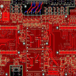
Navigation PCB: GNSS Receiver Layout and Design
A navigation receiver listens for signals that arrive from satellites twenty thousand kilometres away, after passing through the atmosphere and through the product’s own enclosure. The signal at the antenna is well below the thermal noise floor of the receiver, and the position fix depends on recovering it. A navigation PCB is therefore designed around a front end that must add as little noise as the physics allows.
The Receive Chain
The signal path begins at the antenna, passes through a filter, a low noise amplifier and a cable or a matching network, and then reaches the receiver module or the radio frequency front end of the chip. Each element adds loss or noise, and the contribution of the first stages dominates the overall figure.
The consequence is that the amplifier gain and its noise figure, and the loss between the antenna and the amplifier, set the sensitivity of the whole product. Everything after the first amplifier is a much smaller contribution, which is why the layout effort is concentrated at the front.
Antenna Interface
An active antenna contains its own amplifier and takes power from the receiver, delivered on the same coaxial line through a bias tee. The bias network must not load the signal path, and its inductor has to present a high impedance in the band while passing the supply current.
The feed line from the connector to the receiver is a controlled impedance line, and any connector, filter or matching component in it must maintain that impedance. Impedance control across the whole path is not a refinement here: a mismatch reflects part of a signal that is already barely detectable, and it changes the effective noise figure of the front end.

Low Noise Amplifier and Supply
The low noise amplifier is a device whose noise figure is quoted at a specific source impedance and bias, and both must be reproduced on the board. Its supply needs to be exceptionally quiet, because any noise on the bias point is amplified along with the signal.
That means a dedicated regulator, placed away from the switching supplies, with filtering close to the device and a ground return that does not carry the converter current. The design approach is the same as for any sensitive front end, and the reasoning is set out in mixed signal PCB design guidelines.
Ground Plane and Front End Layout
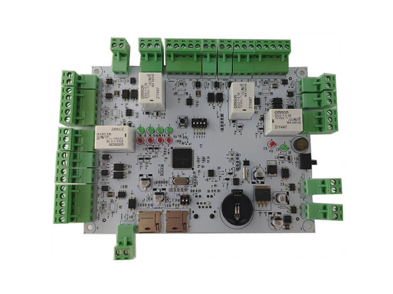
The front end needs a continuous ground plane under it, with no gaps and with stitching vias connecting the top side ground to the reference layer at intervals along the line. The plane is the return path for the radio frequency current, and any discontinuity in it is a discontinuity in the signal path.
Component placement should keep the amplifier as close to the connector as possible, with the filter between them, and the input and output of the amplifier should be separated to prevent oscillation at the gain involved. The transmission line options that suit this kind of front end are compared in microstrip and stripline routing.
Interference from Digital Circuitry
GNSS signals arrive at about minus one hundred and thirty decibels relative to a milliwatt, and a processor clock produces harmonics many orders of magnitude stronger. The receiver must therefore be protected from its own host, which is a layout problem before it is a filtering problem.
The physical separation of the antenna from the digital section, the orientation of the antenna with respect to the display and the board edge, and the routing of the digital buses away from the front end are the primary defences. Filters and shields then address what remains, using the techniques described in EMI suppression design principles.
Timing and Clock Quality
The reference also determines how quickly the receiver can reacquire after a signal loss, which matters in a vehicle that passes under trees or between buildings. The receiver derives time from the satellite signals, and its own clock determines how precisely that time can be reproduced. A jittery reference degrades the tracking performance and, in a product that outputs a timing signal, degrades the accuracy of the output.
The crystal or oscillator should be placed close to the receiver, with a short, well referenced connection and a clean supply. Temperature compensation is relevant for products that must hold accuracy across the operating range, and the thermal design should keep the oscillator away from the components that heat up in use.
Enclosure and Mechanical Design
The antenna needs a clear view of the sky, which constrains where the board can be mounted and how the enclosure can be built. A metal enclosure around the antenna blocks the signal, and a conductive coating on a plastic cover does the same thing.
The ground plane around a patch antenna is part of the antenna, and its size affects the radiation pattern and the centre frequency. In a compact product the plane is smaller than ideal, which narrows the bandwidth and shifts the tuning, so the antenna should be matched with the final mechanics in place rather than on a bare board.
Applications and Their Differences
A handheld navigation device is constrained by size and battery life, and its antenna is compromised by the small ground plane. An automotive unit has more space but must work under a dashboard temperature range and tolerate the vehicle electrical environment.
An industrial or survey grade receiver adds a correction link, often a radio or a cellular module, and the two radios must coexist without desensitising each other. That coexistence problem is solved by filtering and by physical separation, and it is worth planning before the layout rather than after the first sensitivity measurement.
Test and Verification
Sensitivity is measured by establishing the minimum signal level at which the receiver still acquires and tracks, which requires a calibrated signal source rather than a live sky test. The measurement should be made with the product assembled, since the enclosure and the battery affect the antenna.
The noise figure of the front end is measured separately with a noise figure analyser, because it identifies whether a sensitivity shortfall comes from the front end or from interference. Carrying out both measurements on every design revision is what turns a marginal receiver into a predictable one. A shortfall that appears only when the enclosure is closed is almost always coupling rather than front end noise, and the two measurements distinguish between them quickly.
FAQ
Can the antenna be placed inside a metal enclosure? No. The antenna must be outside the metal or behind a non conductive window, and the surrounding ground plane size must be part of the design rather than an accident of the outline.
Does the front end need its own regulator? In practice yes. Sharing a rail with the digital section couples switching noise directly into the most sensitive node in the product.
Why does the fix take longer indoors? Attenuation and multipath reduce the signal to noise ratio, and the receiver needs longer to recover the navigation message. Improving the front end noise figure or the antenna gain is the only real remedy, and both are decided by the layout and the parts rather than by anything the software can do.