Panel Thickness Measurement After Lamination
Panel thickness after lamination is one of the few characteristics that is set by a mechanical process rather than by a chemical one, and it is measured on every lot because everything downstream depends on it. The press closes to a defined gap, the prepreg flows and cures, and the result is a panel whose thickness is determined by the press, the tooling and the material rather than by the artwork.
Measurement is where the tolerance becomes real. A panel measured at one point with a hand gauge passes or fails on the location of that point, and a panel measured while it is still hot reads differently from one that has cooled. Getting the method right takes a few minutes and it is what makes the numbers comparable between shifts and between suppliers.
What Panel Thickness Controls
Thickness controls the electrical behaviour of the board, because the impedance of a controlled line depends on the dielectric separation between the conductor and its reference plane. It also controls the mechanical behaviour of the finished assembly, including the stiffness that resists warpage during reflow and the spacing that a connector or a card guide expects.
In fabrication it controls the drilling depth, the plating current density and the aspect ratio of every hole. A panel that is 0.1 mm thicker than its nominal changes the aspect ratio on a small hole enough to move the plating window, which is why thickness is measured before the drill room rather than after it.
Where the Tolerance Comes From
The nominal thickness is the sum of the core, the prepreg and the copper, and each of those has its own tolerance. The prepreg contributes the largest uncertainty because the resin flows out of the stack during the press cycle, and the amount that flows depends on the resin content, the press cycle and the copper distribution on the layers.
A typical finished tolerance for a multilayer panel is plus or minus 10 percent of nominal, or a stated range such as 1.50 to 1.65 mm for a 1.6 mm construction. The tolerance that matters is the one the design depends on, and a board with a controlled impedance requirement usually needs a tighter window than a general purpose board.
Measuring Instruments and Their Errors
Contact instruments, a micrometer or a snap gauge, are the usual production tools. The relevant errors are the contact pressure, the foot diameter and the calibration of the instrument itself. A gauge with a large foot bridges over a slight depression in the surface and reads high, and one with a small foot reads the local value rather than the panel average.
Non-contact methods, including laser triangulation and ultrasonic measurement, avoid the contact pressure but introduce their own errors from surface finish and from the reference. Whichever method is chosen, it has to be stated in the specification, because a panel measured with an ultrasonic gauge and one measured with a micrometer do not necessarily agree.
Where to Measure on a Panel
The measurement position has to be defined. A point in the middle of a large copper plane reads differently from a point in a bare laminate area, because the copper raises the surface slightly and the resin flows differently around it. Measuring at panel corners and at the centre is the usual compromise, and the positions are marked on a diagram rather than described.
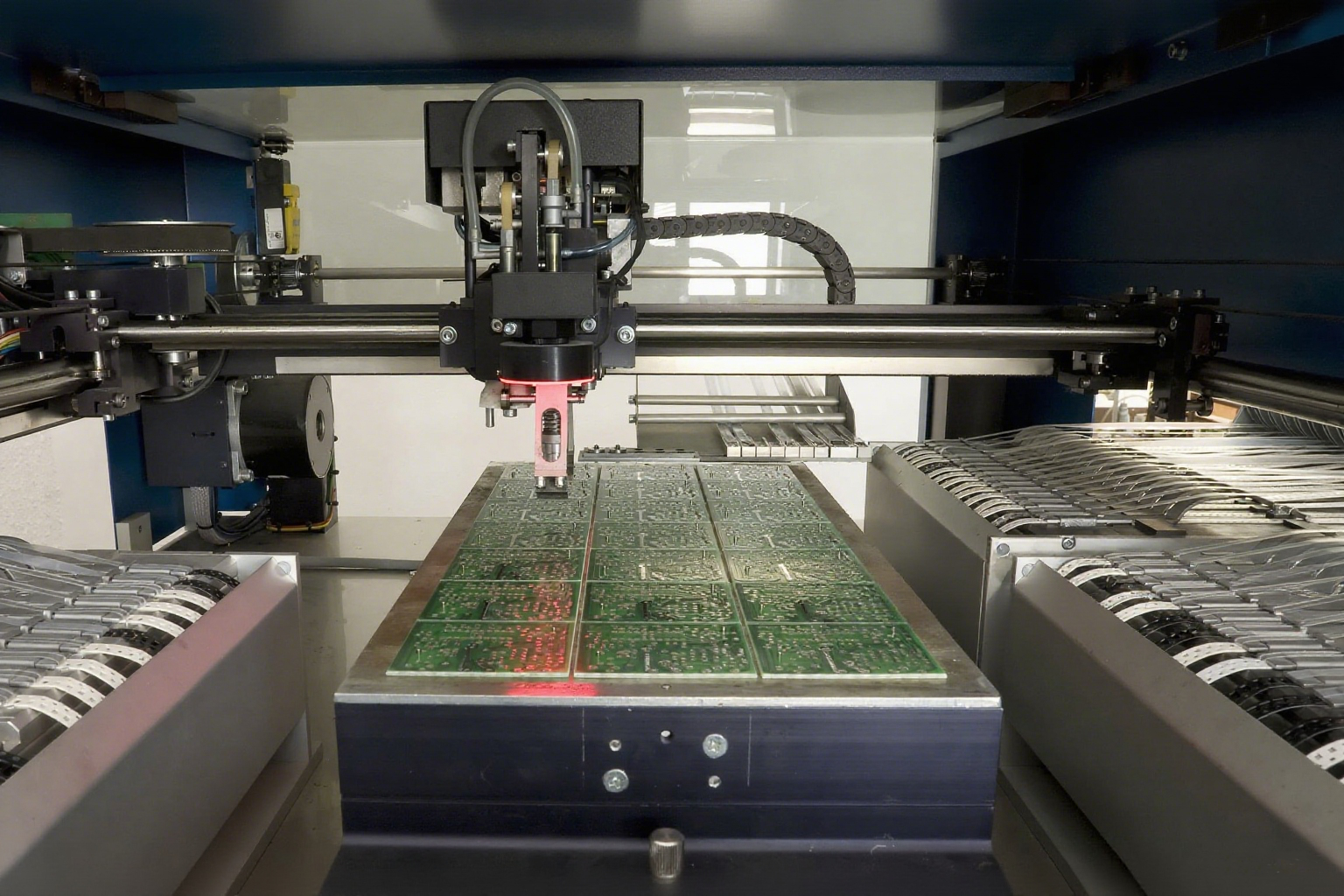
The same positions are used every time so that the readings form a comparable set. Where a panel is measured for acceptance and for process control, the two sets of readings should come from the same locations, and the record should carry the map rather than a single average. The construction side of the same measurement is described in the notes on stack-up tolerance.
Thickness Variation Across a Panel
The variation across a panel is as important as the absolute value. A press that is not parallel produces a wedge, with one edge thicker than the other, and a press with an uneven temperature distribution produces a panel that is thicker in the hot areas because more resin has flowed. Both appear on the map and neither is visible in a single reading.
The variation also affects yield. Where the tolerance is tight, a panel whose average is nominal can have an edge outside the limit, and the board that is cut from that edge is the one that fails the impedance test. The practical response is to measure at the extremes rather than at the centre, so that the reported range describes the panel.
Thickness and the Press Cycle
The press cycle controls the flow of the resin and therefore the final thickness. The ramp rate, the pressure, the dwell at temperature and the cooling rate each influence how much material leaves the stack, and a change in any of them moves the thickness without any change to the materials. A press cycle that is stable produces a thickness that is stable.
Tooling is the other half. A worn or bowed caul plate, a press platen with a temperature gradient across it and a tooling plate that is not flat all transfer their own shape to the panel. The maintenance of that tooling appears in the thickness record long before it appears in a visible defect, and the maintenance practices are described in the notes on tooling plate maintenance.
Thickness and Downstream Processes
Drilling uses the panel thickness to calculate the depth of every hole and the aspect ratio that the plating has to meet. A thickness that is outside its window therefore moves the plating requirement, and a thick panel with a small hole can push the aspect ratio past the point where the process holds its minimum barrel copper.
The assembly process sees the same number. Board thickness sets the spacing of the conveyor rails, the height at which the stencil sits and the thermal mass that the reflow profile has to heat. A panel that is at the top of its tolerance behaves like a heavier board, and the note on the drawing is what tells the assembler to expect it. The cycle that produces the thickness is described in the notes on lamination cycle parameters.
Records and Trending
The record for a lot should contain the nominal and the tolerance, the instrument and its calibration, the measurement positions, the individual readings and the range, and the press and tooling identification. That set of fields allows a thickness change to be attributed to a material lot, a press cycle or a tooling change within one review.
Trending the mean and the range over several lots is what converts the record into a control. A mean that drifts slowly points to tooling wear or to a prepreg lot change, while a range that widens points to a press problem or to an uneven stack. Both are visible before a lot fails, and both are corrected with a maintenance action rather than with a scrap.
Reacting to a Drift
The first check is the press cycle record, because the parameters are easy to compare and the presses are usually instrumented. The second is the tooling, including the caul plates and the platens, which can be measured with a straight edge and a feeler gauge without dismantling the press.
Where a single lot is affected, the material is the likely cause, and the laminate and prepreg certificates should be compared with previous lots. Where every lot on one press is affected, the press or its tooling is the cause. That decision is the point of keeping the press identification in the record, and the coupon practices that support the same investigation are described in the notes on copper thickness coupons. Measurement of the finished board flatness, which depends on the same variables, is covered in the notes on warpage measurement.
FAQ
Should thickness be measured hot or cold? Cold, after the panel has returned to room temperature. A hot panel reads thicker because of thermal expansion, and the difference is larger than some tolerances.
Why do the edges of a panel measure differently from the centre? The resin flow and the press temperature are not uniform, so the thickness varies across the panel. Measuring at the extremes describes the panel better than a reading at the centre.
Does a thicker panel always fail? Only against its own tolerance. The consequence is a change in aspect ratio, impedance and assembly behaviour, and the design tolerance is what decides.