PCB Depanelising Tooling Selection
Depanelising is the step where the finished boards are separated from the panel, and it is also the step that damages more assemblies than any other mechanical operation. The tooling choice determines the edge quality, the stress on the components and the cycle time.
The decision follows from the panel design, since the break method has to match the tab or the score that the fabrication data specified. Choosing the tool after the panel is designed often means living with a compromise.
Manual Snapping
Snapping by hand with a simple fixture is the cheapest method and the one with the most variation. The result depends on the operator, on the fixture and on the panel, and the edge quality varies between shifts.
It is acceptable where the edge is not visible and the components are far from the break line. Where either condition fails, another method is needed.
Routing Machines
A router cuts the tabs with a rotating bit, which gives a clean edge and a repeatable result. The bit follows a program derived from the panel data, and the cut depth and speed are controlled.
The method produces dust and static, both of which affect a sensitive assembly, so extraction and ionisation are part of the installation rather than accessories.
Laser Depanelling
A laser cuts without mechanical contact, which removes the stress entirely and allows a complex outline. The cut edge is clean and the method suits a brittle component or a flexible assembly.
The cycle time is longer and the capital cost is higher, so the method is used where the value of the assembly justifies it.
V-Cut Breaking
A V-cut is broken with a bar or a roller, which applies a controlled bending moment along the score. The result is a straight edge with a bevel, and the method is fast.
The limitation is the geometry, since the score must be straight and the components must be clear of the line. Both constraints are described with the panel design in panelisation and tab routing.
Stress and Component Damage
Every depanelising method applies force to the board, and the force travels to the nearest components. A ceramic part near a break line is the component most likely to be damaged.
Supporting the board directly under the break line is the most effective measure, and it is cheaper than changing the method. The damage mechanism is the one described for chip component cracks.
Edge Quality
The edge may need to be free of burrs, of loose fibres and of roughness, depending on whether it is visible or whether it slides into a housing. The requirement should be stated rather than assumed.
A routed edge and a snapped edge are visibly different, and a customer expecting one will reject the other. The drawing should specify the method or the acceptance criterion.
Throughput and Changeover
The cycle time of the method determines how many operators are needed, and the changeover determines how the method handles a mix of products. A router needs a program per panel, while a manual fixture needs a different fixture.
Where the product mix is wide, the changeover time can exceed the cutting time, which is the argument for a programmable method.
Handling After Separation
Boards that have been separated are loose units, and they are handled individually from that point. The handling should be defined for the equipment that follows, since the loose part of the process is where damage occurs.
Where possible, the depanelling should occur as late as possible, so that the boards are handled as a panel for as long as the process allows.
Records
The method, the tooling and the support arrangement should be recorded for each product, together with any damage found. Where a crack appears in the field, that record is where the investigation starts.
It belongs with the process evidence described for manufacturing processes.
Additional Considerations for This Build
Practical attention to depanelising tooling pays for itself here, because it decides whether the finished board behaves as the drawing intended. Where the requirement is not stated on the fabrication drawing or in the assembly notes, the shop has to assume a default, and that default is rarely the value the design was simulated with. Stating depanelising tooling explicitly, together with the tolerance that applies, removes the assumption and keeps the result predictable from batch to batch.
Deliberate attention to laser cutting pays for itself here, because it decides whether the finished board behaves as the drawing intended. Where the requirement is not stated on the fabrication drawing or in the assembly notes, the shop has to assume a default, and that default is rarely the value the design was simulated with. Stating laser cutting explicitly, together with the tolerance that applies, removes the assumption and keeps the result predictable from batch to batch.
Process Control and Verification
On a design of this kind, router is the item that decides how the rest of the board is arranged. The measurements that matter are the repeatable ones: conductor width and spacing, annular ring, finished hole size, plating thickness and surface finish are all verifiable on a coupon that travels with the panel. Running a first article through the same checks as the production panel confirms that the two agree, and that comparison is the cheapest form of process control available at prototype stage.
Keeping a sample from the panel turns a dispute into a measurement, because the same coupon can be re-examined by both parties without rebuilding the batch. Reviewing the design before the data is released is cheaper than correcting it after the panel is in the tank, because every step downstream inherits the decision made at the front end.
Documenting the assumption is part of the design work, and a short note on the drawing prevents a question that would otherwise arrive a day later and cost a day of schedule. The process window is set by the narrowest step in the flow, so an improvement anywhere else shows up as margin rather than as yield until that step is addressed.
A short note on the drawing about handling, storage or packaging is often worth more than an extra decimal place on a tolerance.
Process Control and Verification
On a design of this kind, router is the item that decides how the rest of the board is arranged. The measurements that matter are the repeatable ones: conductor width and spacing, annular ring, finished hole size, plating thickness and surface finish are all verifiable on a coupon that travels with the panel. Running a first article through the same checks as the production panel confirms that the two agree, and that comparison is the cheapest form of process control available at prototype stage.
A first article check confirms that the process and the drawing agree on the points listed above, and that the coupon data supports the values used in the design.
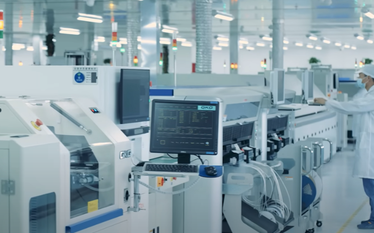
Where a measurement falls outside the expected window, the sample is retained so that the cause can be established before the balance of the batch is released.
A first article check confirms that the process and the drawing agree on the points listed above, and that the coupon data supports the values used in the design.
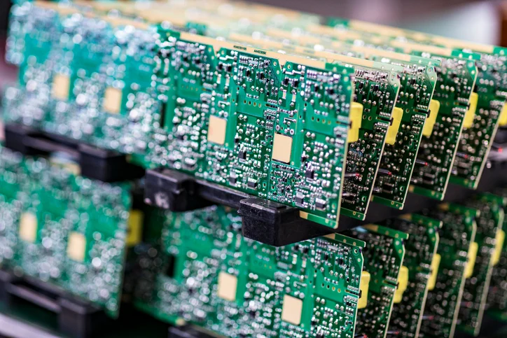
Where a measurement falls outside the expected window, the sample is retained so that the cause can be established before the balance of the batch is released.
FAQ
Which method damages components least? A laser, because it applies no mechanical force, followed by routing with proper support.
Can a router cut a curved outline? It can follow any path in the program, which is one of its advantages over a V-cut.
Does depanelling create static? Router dust and the separation itself can, so ionisation is used on the machine.
When should the method be chosen? At panel design time, because the break feature and the tooling have to match.