PCB Drilling Process: Mechanical Versus Laser Drilling
Every hole in a circuit board is a decision about how the board will be built. The PCB drilling process sets the smallest feature the design can use, the registration window the layers must meet, and a large part of the cycle time and cost of the finished panel.
Two technologies dominate. Mechanical drilling cuts material with a rotating tool, while laser drilling removes material with focused energy. They are not competitors in every case; understanding where each one belongs is what separates a cost effective process plan from an expensive habit.
Why Drilling Decides Everything That Follows
Holes determine electrical performance as much as mechanical structure. A plated barrel connects the layers that carry both signal and power, and its quality affects resistance, inductance and long term reliability. A hole that is slightly out of position can reduce the clearance to a plane it was never meant to touch.
Because drilling sits early in the sequence of board fabrication, defects created there are amplified by every later step. Poor wall quality leads to plating defects, plating defects lead to open circuits, and open circuits are only discovered at final test after the entire material and processing investment has been spent.
Cutting Versus Ablation
Mechanical drilling is a contact process. A tungsten carbide or diamond tool spins at high speed and shears material away layer by layer, producing a hole with a defined wall and a small amount of smear that has to be removed before plating.
Laser drilling is non contact. Focused energy vaporises or melts the resin and copper at a precise location, leaving no tool marks and no tool wear. The trade off is that energy behaves differently in different materials, so the correct parameters depend on the resin system, the glass fabric and the copper foil involved.
What Mechanical Drilling Does Best
For through holes in conventional multilayer boards, mechanical drilling remains the most efficient method available. Tool change is simple, the process is mature, and the equipment is understood by every operator on the floor. Cost per hole falls quickly as volume rises.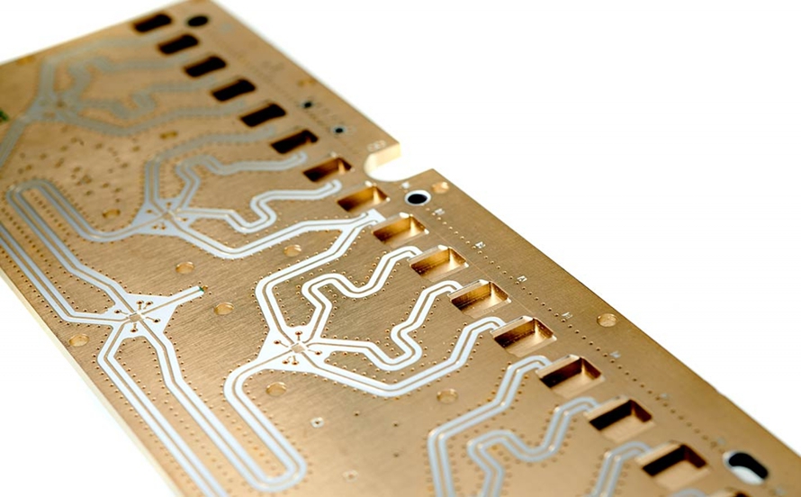
It also handles the materials that lasers struggle with. Heavy copper, thick laminates and standard FR-4 constructions where the copper weight exceeds a few ounces are all well served by a carbide tool, provided the drill parameters match the stack rather than being copied from a previous job.
The Limits of a Spinning Tool
Miniaturisation is where mechanical drilling meets its ceiling. Below roughly a tenth of a millimetre, tool breakage becomes common, and the cost of each tool rises as the diameter falls. A broken drill inside a panel usually destroys more than the hole it was making.
Aspect ratio is the second limit. Long, thin tools deflect, wander and snap, which becomes critical as board thickness grows with layer count. High layer count stacks are therefore exactly the products where mechanical drilling alone becomes impractical, and where the process has to change.
How Laser Drilling Removes Material
A laser drill creates a blind via by removing the dielectric down to the pad beneath it, or a through hole by repeated pulses through the full stack. There is no mechanical force, so thin materials are not distorted and fragile constructions are not damaged by contact.
The process demands tight control of energy density, pulse width and focus position. Too little energy leaves residue in the via bottom, and too much energy damages the pad and the laminate around it. Both failures are easy to create and hard to detect without cross sectioning.
Ultraviolet, Infrared and Ultrafast Sources
Different wavelengths interact with different materials. Ultraviolet sources are absorbed efficiently by polymers and produce a clean cut with limited thermal damage, which is why they are widely used for microvias in HDI constructions and for flexible substrates.
Infrared sources remove copper more readily and are often used where copper has to be opened directly. Ultrafast sources reduce heat input further, at higher equipment cost. The right choice depends on the material stack and on the feature size the product actually requires.
Feature Size and Aspect Ratio
The practical difference between the two processes shows up in two numbers. A mechanical process typically works from about 0.15mm downward with increasing difficulty, while laser processes can reach 0.05mm or smaller depending on material and plating capability.
Aspect ratio moves the same way. A laser drilled microvia can exceed ten to one and, in specialised builds, reach considerably further, while a mechanical tool becomes unreliable well before that point. Higher aspect ratio means deeper structures and more routing freedom in the same panel area.
The Cost Structure Is Not What It Appears
Laser equipment costs several times more than mechanical drilling equipment and often needs gas assist systems, so the initial investment looks steep. But the laser consumes no drill bits, and tool cost is a recurring expense that grows quickly as hole diameters shrink.
The correct comparison is total cost per acceptable hole, not equipment price. That figure includes tool replacement, downtime for tool changes, scrap from broken drills and the labour required to inspect and rework panels after a drilling problem.
Throughput Depends on the Order Mix
Mechanical drilling produces throughput steadily when the same design runs for hours. Laser systems can be arranged with multiple positions and change programs quickly, which suits a mix of small and varied orders better than it suits one standard product.
Factories that run both processes therefore schedule differently. High volume standard designs go to mechanical lines, while dense, high value or frequently revised products go to laser. Mixing the two badly wastes capacity on both sides of the shop.
When Higher Layer Counts Force the Choice
Layer count has become the dividing line in much of the market. Boards in the four to twelve layer range are usually drilled mechanically without difficulty, and adding laser capacity would not improve either quality or cost on those products.
Above roughly sixteen layers, the calculation reverses. Deep stacks make mechanical tools fragile, and the routing pressure of dense designs demands smaller vias anyway. At that point the production process has to include laser drilling as a standard step rather than an exception.
Heavy Copper and Hard Materials
Power electronics bring copper weights that resist laser processing. A thick copper layer reflects energy and conducts heat away from the drilling point, making clean ablation difficult. Mechanical drilling cuts through such material without complaint, provided the tool and the feed rate suit it.
This is why power boards remain a mechanical process stronghold. Copper in the range of three ounces and above, thick laminate and generous hole sizes all favour the conventional approach, and the resulting holes plate well because their walls are clean and accessible.
Flexible and Rigid Flex Substrates
Thin, compliant materials behave badly under a spinning tool. A flexible base film can deflect as the drill enters, producing an oversized or torn hole, and a rigid flex construction mixes two material systems that respond differently to the same parameters.
Laser processing suits these products because it applies no mechanical load. Flexible circuit assembly work therefore depends heavily on laser drilling for microvias in the flexible regions, while the rigid sections may be handled mechanically where the geometry allows.
Hybrid Drilling as the Practical Answer
Most complex products are built with a combination. Mechanical tools create the through holes and the larger vias that carry power, while laser sources create the microvias that release routing space in the densest sections. Both processes are planned together rather than chosen once for the whole board.
Hybrid planning reduces cost without harming performance. A designer who understands which layers genuinely need microvias, and which can be served by a conventional hole, gives the factory room to balance quality against price instead of optimising one at the expense of the other.
Supporting Steps That Are Rarely Mentioned
Drilling quality depends on preparation and follow up. Entry and exit materials control burring, desmear removes resin residue from the barrel before plating, and panel baking prevents moisture from vaporising inside a thick stack and damaging the inner walls.
None of those steps appears in a PCB datasheet, yet each one influences process control and final yield. Factories that manage them consciously produce consistent holes; factories that treat them as fixed settings eventually discover the cost of a variable they stopped watching.
How to Specify Drill Capability to a Supplier
Ask for capability in numbers rather than categories. Minimum laser via diameter, achievable aspect ratio, drilling tolerance and the largest copper weight the factory processes routinely are all measurable, and a supplier who knows its process can quote them without hesitation.
Then ask which process will be used for the specific design being quoted. A quote that names the drilling method, the material assumptions and the inspection step is a technical commitment. A quote that only names a price is a question waiting to become a delay, and a supplier who cannot quote numbers has probably not measured its own process recently.