PCB Fabrication Capability: Two to Thirty Layers
PCB fabrication covers a wider range than most buyers expect when they first place an order. The same shop can cut a two layer prototype on a Friday and laminate a thirty layer backplane over the following fortnight, and the reason those two orders behave so differently is that the layer count is not a quantity but a change in the nature of the process. This overview sets out the range that is actually in production and the points at which a design starts to require something other than the ordinary route.
The Range in Production
Two layer boards are the simplest and the fastest class, used for the majority of control boards, power distribution and simple interfaces. Four layer boards add a dedicated power and ground pair and are the standard choice when a design has a mixed signal content or a moderate component density. Six and eight layer boards introduce the routing space that a modern processor requires and are where impedance control starts to be applied as a matter of course.
From ten layers upwards the boards are usually digital systems with several high speed interfaces, or backplanes, and the fabrication becomes a stack-up engineering exercise rather than a routing exercise. The laminate sequence, the prepreg combinations and the copper weights on each layer are chosen together, because the electrical behaviour and the mechanical stability of the finished board both depend on that combination.
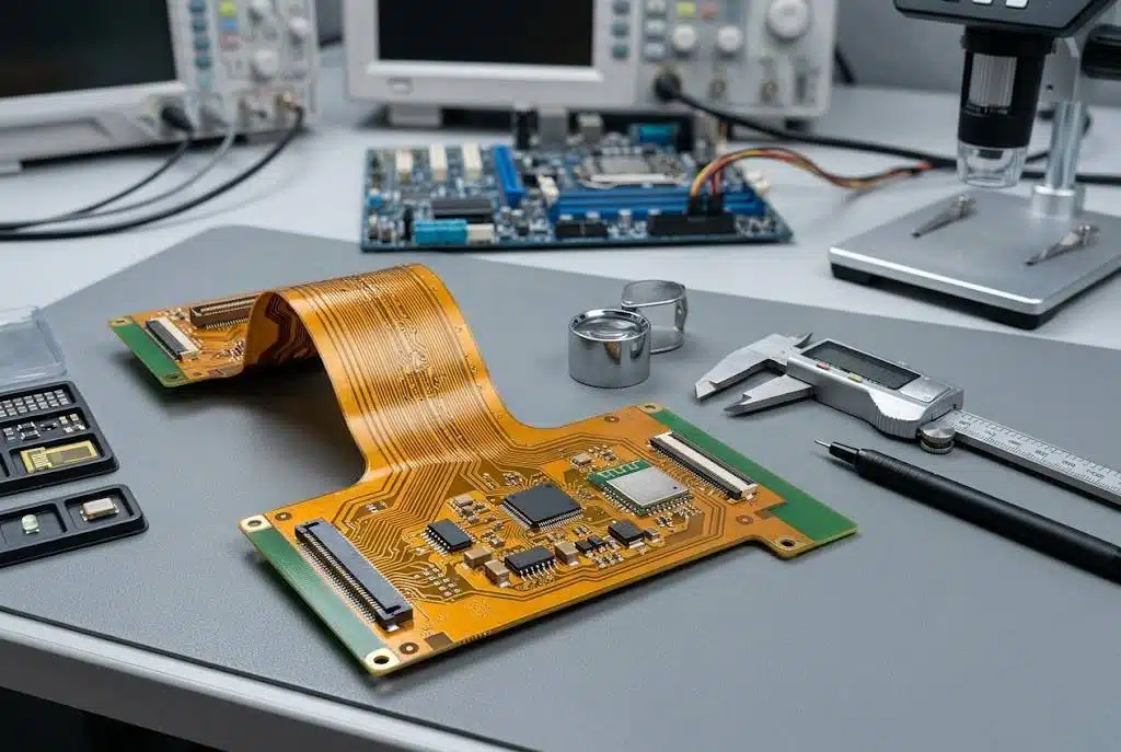
Special constructions sit alongside the layer range rather than outside it. Blind and buried vias, high frequency laminates, aluminium and copper cores, heavy copper, and rigid flex assemblies each add a class of operation to the route.
What the Stack-Up Decides
The stack-up is the document that controls the rest of the fabrication. It fixes the dielectric thickness between each pair of layers, and therefore the characteristic impedance of every controlled trace. It fixes the copper weight, and therefore the current capacity and the thermal performance of the power distribution. It fixes the total thickness, and therefore whether the finished board will fit the connector it is supposed to fit.
A stack-up that is written after the layout is a description of what happened. A stack-up that is written before the layout is a set of constraints that the routing respects. The second version is the one that saves a revision, because a designer who knows the dielectric thickness and the trace geometry can hit the impedance target on the first pass rather than discovering the mismatch when the coupon is measured.
Layer to layer registration is the fabrication consequence of a tall stack. Each lamination cycle adds a registration step, and the tolerance of the finished board is a function of the number of cycles rather than of the care taken in any single one, which is why the high layer count boards are inspected by X-ray after pressing.
Materials and Their Consequences
The default laminate is a standard FR-4 grade, and for many products it is entirely sufficient. When the operating temperature rises, when the dielectric loss becomes significant at the frequencies in use, or when the dielectric constant has to be held within a narrow band, a higher performance material is specified. Each step up in performance brings a change in drilling parameters, in the lamination cycle and in the cost, so the decision is taken from the requirement rather than from a preference.
The copper weight is the other material decision that changes everything downstream. Heavier copper affects the etch resolution, the minimum achievable spacing and the plated hole quality, which is why a design that needs heavy copper for current carrying is reviewed against the capability before the artwork is converted rather than after.
Surface Finish
The surface finish is chosen from the assembly process and the storage requirement rather than from habit. A hot air levelled finish is inexpensive and robust for a board that will be soldered promptly; an electroless nickel immersion gold finish gives a flat surface that suits fine pitch assembly and a longer shelf life; an organic solderability preservative gives a flat copper surface at low cost and a shorter window before storage conditions begin to matter. A board that is stored for months before assembly has a different requirement from one that is placed within a week.
Inspection and Test Across the Range
Whatever the construction, the finished board is electrically tested for open and short circuits, and the appearance and dimensions are inspected against the acceptance standard. The checks that sit around those two gates scale with the difficulty of the board. High layer count products are inspected for registration after lamination, impedance controlled products carry a coupon and a measurement report with the batch, heavy copper products are checked for the plated quality of the holes, and boards with copper in the hole are verified by cross section.
Special constructions receive their own attention. Blind and buried via boards are held to a tight registration window with resin or plating fill, and their barrel quality is verified by sectioning. Rigid flex assemblies are inspected at the transition between the flexible and the rigid sections, which is where the mechanical risk is concentrated. High frequency boards are held to a stable dielectric constant so that the analysis used in the design remains valid in the product.
Matching the Board to the Route
The practical value of a capability overview is that it allows a design to be matched to a route before the order is placed. A board that requires a controlled impedance, a heavy copper inner layer and a blind via sequence at the same time is buildable, but it is not an ordinary order, and the schedule and the cost both reflect that. Knowing the difference at the quotation stage is worth more than any later negotiation. The limits are stated on the PCB capabilities page, the flow that a board passes through is described under process, the fabrication records sit with quality management, and the finished board moves into SMT assembly and PCBA testing.
Where the Cost Actually Sits
The price of a fabricated board is not evenly distributed across the operations, and knowing where the money sits changes what a designer does about it. The panel utilisation is the first factor: the same board placed on a panel that wastes a third of its area costs materially more than one that nests efficiently, and the shape of the outline is often adjustable at the layout stage. The layer count is the second, not because the material is expensive but because each pair of layers adds a lamination cycle, a registration step and a set of inspections.
The via construction is the third. A through hole via is drilled and plated in the same pass as every other hole on the board and adds almost nothing to the cost, while a blind or buried via requires the layers to be built and pressed in a sequence, which multiplies the number of operations. A designer who can route the board with through vias rather than adding an HDI sequence usually saves more than the routing space is worth.
The finish is the fourth. A finish that is specified out of habit rather than from the assembly requirement adds cost on every panel without improving the result. Reading the surface finish decision as a function of the assembly process and the storage period, rather than as a default setting, is one of the simplest savings available.
How a Capability Question Is Answered
Most capability questions are answered in one of two ways: by comparing the design against the published limits, or by sending the data in for an engineering review. The published limits cover the routine characteristics such as the minimum line width and spacing, the drill sizes, the aspect ratio, the copper weights and the profile tolerance. A design that stays inside those limits can be quoted directly.
A design that touches the limits, or that combines several demanding characteristics in one board, is better assessed from the data. A short review confirms whether the combination is buildable, which operations it needs and where the risk lies, and the answer arrives before the order is placed rather than after the panels have been imaged. That review is also where a design that is nearly within the limits can be adjusted slightly to avoid a costly operation, which is a conversation worth having while the artwork is still editable.
FAQ
Does a higher layer count always cost more? It costs more in fabrication, but it can reduce the total cost by removing the need for a second assembly pass or a larger board area.
When is the stack-up decided? Before the layout, so that the impedance and the current path are designed to it rather than checked against it afterwards.
How is the surface finish selected? From the assembly process, the pitch of the devices and the storage time before soldering, rather than from a general preference.