PCB Panelization: Why Boards Are Combined
A small board is difficult to manufacture and even more difficult to assemble. It does not fit the fixture, it does not feed through the placement machine reliably, and it wastes panel area if it is produced one at a time. PCB panelization is the answer: several copies of the circuit, and often several different circuits, are laid out together on one larger panel that the equipment can handle. The arrangement looks like a mechanical detail and is in fact one of the decisions that most affects cost and yield.
Why Small Boards Are Combined
A panel exists because every machine in the line has a working range. Below a certain size a board cannot be clamped in a fixture, cannot be conveyed reliably, and cannot be printed with consistent paste. Combining several boards into one panel brings the dimensions back into that range without changing the product.
There is a second reason, which is material utilization. A board with an irregular outline leaves unusable area around it on the panel. Nesting several parts, or placing a small part in the space left by a larger one, recovers area that would otherwise be scrapped, and the savings in laminate are direct. Panelization therefore improves assembly throughput, uses the equipment more efficiently, and reduces the material thrown away.
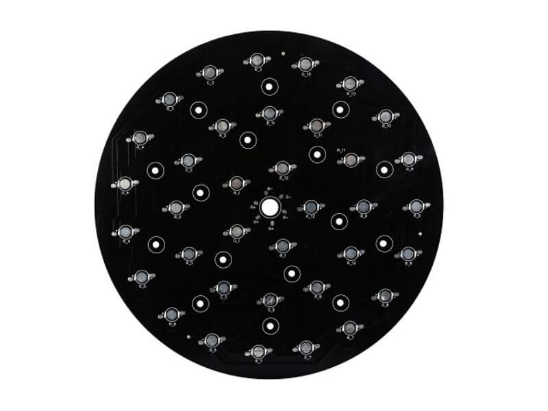
<img src="https://www.gopcba.com/wp-content/uploads/2026/01/Макро-изображения-поверхности-PCB-с-покрытием-ENIG.jpg" alt="PCB panel with several circuits combined and a working edge” />
Working Edges and Handling
Most panels carry a working edge, a strip of material along one or two sides that exists only to be gripped by the conveyor and the placement machine. The edge is not part of any product and is removed before final assembly or left on until the panel is depaneled. Its width is set by the equipment rather than by the design, and the components must be kept far enough from it that the tooling does not touch them.
The working edge is also where the panel is stiffened. A panel that flexes during handling will not place components accurately, so the edge and any internal rails are what keep the assembly flat through printing, placement, and reflow. Where a panel needs extra rigidity, the answer is usually more material at the border rather than a thicker board, because the product thickness is already fixed by the design.
How the Pieces Are Separated
Three methods cover most cases. V-scoring cuts a partial groove along a straight line, so the pieces snap apart after assembly; it requires a straight edge and leaves a small witness mark. Tab routing leaves small bridges of material that are cut afterward, which allows curved outlines and free placement but requires a routing step. Perforation or a series of small holes is a cheaper third option for simple shapes and lower volumes.
The separation method interacts with the outline and the copper clearance. A V-score line has to be straight and continuous, and any copper within the scoring depth will be damaged, so the edge clearance rules matter more on a panelized design than on a single board. Tab positions have to avoid placing a bridge where it would be cut by a component or a connector, and the tabs themselves need to be wide enough to hold the piece but narrow enough to break cleanly. These constraints are closely tied to the edge geometry described in PCB slot and edge routing rules.
Mirror Panels and Stencil Savings
A mirror panel places the top side of one circuit against the bottom side of the next, so the whole panel is populated on one side in each pass through the line. The immediate saving is a stencil: where two separate panels would each need their own, the combined arrangement can be printed with one. The layout consequence is that the panel has to be designed as a mirror image rather than as a repeated copy, which affects the orientation of every component and the position of every fiducial.
Mirroring also changes the mechanical behavior of the panel. Because the pieces are not identical in orientation, the rail area that supports them has to be arranged differently, and the depanel method has to suit the mirrored pattern. It is a technique worth using when the assembly is heavily one-sided, and not worth forcing when the design is already double-sided.
Material Utilization and Cost
The panel is a material purchase, so its layout is a cost decision. Panel area is fixed by the standard sheet sizes the shop stocks, and the fraction of that area occupied by usable circuits sets the material cost per piece. Nesting a small part into the space left by an irregular one, rotating parts where the grain direction allows, and keeping the gaps between pieces to the minimum the separation method requires are all direct savings.
There is a counterweight. Dropping the gap too far makes the pieces difficult to separate and increases the chance of damage at the edge, and packing too many different circuits onto one panel means that a change to any one of them forces a change to the whole arrangement. A panel that mixes several product types also carries the risk that a single defect in one piece distorts the yield calculation for all of them. The trade-offs between layout and downstream production behavior are discussed in how PCB layout decisions affect production.
What to Specify
Three fields belong on the order. State whether the boards ship as single pieces or on the panel, because that decides how much work the shop does. State whether a working edge is required and how wide, since that follows from the assembly equipment rather than from the design. And where the design already assumes a preferred arrangement, supply it, because a panel that respects the intended component orientation and the intended separation method costs less to tool than one the shop invents from scratch. Where a panel is being designed for the first time, the guidance collected in multilayer PCB prototype requirements is a reasonable starting point.
What matters is that the decision is made consciously. Panelization is invisible in the finished product, so it is easy to leave entirely to the shop, and a panel that suits the shop rather than the assembly line becomes a quiet cost on every unit built.

One practical check remains. Before releasing a panel, confirm that every piece on it carries the same process requirement. Mixing a board that needs a thin gold finish with one that needs heavy copper forces the whole panel through the more demanding process, and the cheaper part pays for the expensive one. Grouping parts with similar requirements keeps the process uniform and the cost predictable, and it keeps a change to one product from disturbing the tooling for the others.
It is also worth confirming the fiducials. Placement machines align to marks on the panel rather than to the individual pieces, so the panel needs its own set, positioned where they survive the separation step and remain visible through assembly. A panel without fiducials is placed by the accuracy of the conveyor alone, which is not sufficient for fine-pitch work.
FAQ
Why can a small board not be assembled on its own? Because it falls below the working range of the fixtures, conveyors, and placement machines. The panel brings the handled dimensions back into that range.
What is a working edge for? It is material added along the panel border so the conveyor and the placement machine can grip and transport the panel. It is not part of the product.
When is V-scoring preferable to tab routing? When the outline edges are straight. V-scoring is faster and cleaner, but it cannot follow a curve and it leaves a small witness mark.
Does a mirror panel always save money? Only when the assembly is largely one-sided. It saves a stencil, at the cost of a more constrained panel layout and separation method.