Panelization: Key Checks Before Release
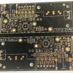
Panelization is the arrangement of boards into an array so that they can be processed as one unit. It decides how the boards are held during assembly, how they are separated afterwards and how much of the panel is spent on material that will be thrown away. A good panelization is invisible in production; a poor one shows up as broken corners, cracked joints and a stencil that does not sit flat.
What the Array Has to Do
The array holds the boards rigid during printing, placement and reflow, provides the fiducials that the machine uses for alignment and gives the conveyor something to grip.
It also has to survive depaneling without transferring a stress into the board, and it has to allow the finished board to meet its outline tolerance after separation.
Those requirements pull in different directions. A rigid array uses more material and more tabs, while a light one is easy to separate and less stable during assembly.
Array Layout
The boards are arranged in a grid with a gap between them, and the gap is the space that the depaneling tool will travel through. A router needs a gap wide enough for the bit, while a scoring wheel needs a straight line that crosses the whole panel.
A mixed array can combine different boards, which improves the material utilisation, but it also mixes the assembly programs and the traceability. The gain is worth it where the products have similar volumes.
The array orientation should match the board’s routing direction where the assembly line has a preferred direction, and the fiducials should be placed so that a machine can see at least two of them without moving the panel.

The Gap and the Web
The gap between the boards sets the tooling that can be used. A gap of a few millimetres allows a router or a laser, while a v cut scoring line needs the boards to be almost touching.
A web is the material that remains after a scoring operation and it is what holds the board in place. Its thickness is a compromise between the rigidity during assembly and the effort of separation, and it is usually between a quarter and a third of the board thickness.
The web is also what determines whether the separated edge is clean. A web that is too thick tears rather than breaks, and the tear takes a piece of the laminate with it.
Breakaway Tabs
A breakaway tab is a short section of laminate that connects a board to the array. The tabs are placed where the separation force will not reach a component or a solder joint.
The tab should be a defined width and should have a perforation or a routed slot that concentrates the stress at the intended point. The number of tabs is chosen from the board size and the assembly handling rather than from a fixed rule.
A tab that is placed beside a fine pitch package, a ceramic capacitor or a connector can transmit a bend that cracks the joint during separation. The layout should keep the tabs away from those areas and, where that is impossible, the separation should be done with a method that applies no bending.
Fiducials and Identification
Global fiducials are placed on the array in positions that do not interfere with the boards, and local fiducials are placed on the board itself where a fine pitch device needs them.
The fiducial must be visible to the machine after the stencil and the components are in place, so it should not be covered by a component or by a connector. Its contrast should be checked against the finish and the solder mask.
Identification is part of the array. A panel number, a date code and often a board position are marked so that a defect can be traced to a position on the panel, which is what allows a recurring fault to be linked to the equipment.

Depaneling Method and the Array
The array should be designed for the depaneling method. A router needs clearance for the bit and a path that does not cut through a component, while a laser needs a defined kerf and a path that does not damage the adjacent copper.
A hand separation is the least controlled method. It applies a bending moment that the array cannot resist, and its use should be limited to a large board with generous margins and a non critical joint population.
Where the boards are separated by a punch or a die, the array should include the tooling holes that locate the die. A die that is located from the board edge rather than from a tooling hole will produce a varying outline.
Material Utilisation and Cost
The array spends material on the gaps, the tabs and the border. Those areas are part of the panel cost and they should be minimal without compromising the process.
A large array reduces the handling per board, which lowers the assembly cost, and it increases the cost of a defect that affects the whole array after assembly. The balance depends on the value of the boards and on the assembly yield.
A change of array affects the stencil, the fixtures and the test tooling. Those costs should be included when the array is compared, because an array that saves a small amount of material can require a new set of tooling.
Common Problems
A board that is loose in the array during printing produces a deposit that is offset, because the paste follows the board rather than the stencil. That is a rigidity problem and it is solved with more or differently placed tabs.
A corner that breaks during depaneling points at a tab that is too narrow, at a web that is too thick or at a separation method that applies a bend. The repair is a change to the array or to the method.
A stencil that does not sit flat over an array is usually caused by a step between the boards, a raised tab or a warp. The stencil needs a flat surface, and a panel that is not flat will produce a poor deposit regardless of the printer settings.
Practical Rules
Design the array around the assembly line and the depaneling method, keep the tabs away from critical joints and place the fiducials where they can be seen. Check the rigidity before the array is released.
Record the array data with the build records and the breakaway tab design, and review the depaneling methods and the panel size selection when the panel is defined.
FAQ
Where should breakaway tabs be placed? Away from fine pitch packages, ceramic capacitors and connectors, because the separation force can bend the board and crack a joint.
What determines the gap between boards? The depaneling method. A router needs clearance for the bit, while v cut scoring needs the boards almost touching so that the blade can cross the panel.
Why is array rigidity important for printing? A board that moves in the array during the print stroke takes the deposit with it, which produces an offset or a short deposit that no printer setting can correct.