PCB Panelization, Tabs And Depanelization
A single small circuit board cannot be handled economically. It cannot be printed, placed, reflowed or tested on its own without a fixture for every operation, so several boards are assembled into one panel with a frame and a set of rails around them. Panelization is the design of that arrangement, and it decides how much material is wasted, how the boards are separated, how much stress the components see when they are separated, and whether the assembly line can grip the panel at all.
This article covers the reasons for panelization, the constraints that set the panel size, the ways of holding a board in place, and the rules that keep the separation from damaging the product.
Why Boards Are Panelized
The first reason is handling. A panel is large enough to be moved by the rails of a conveyor, printed by a stencil that covers the whole area, and placed by a machine whose fiducials are on the panel rather than on each board. The second reason is throughput, because the placement machine and the reflow oven process a panel in almost the same time as a single board, so the effective rate rises with the number of boards on it.
The third reason is material. The panel is cut from a standard sheet, and the number of boards that fit determines the cost of the laminate per board more than any other decision. A layout that wastes the corners of a sheet can lose more money than a change of laminate would save, which is why panelization is considered at the same time as the board outline rather than after it has been frozen.

What Sets The Panel Size
The panel has to fit the equipment. The conveyor width, the maximum panel dimension that the stencil printer and the placement machine will accept, the reflow oven belt width and the deposition mask of the plating line all impose limits. A common working range is between about 100 and 460 millimetres on the short side and up to 600 millimetres on the long side, with the exact figures taken from the equipment list rather than from a general standard.
A panel that is too small wastes machine time and may not be held by the rails; one that is too large sags under its own weight in the oven, and the sag shows up as a variation in the reflow profile across the panel. The mass also matters, because a heavy panel takes longer to reach temperature and to cool, so the profile that works for a lightly loaded panel will not be the same for a fully loaded one.
Tabs, Perforations And Breakaway
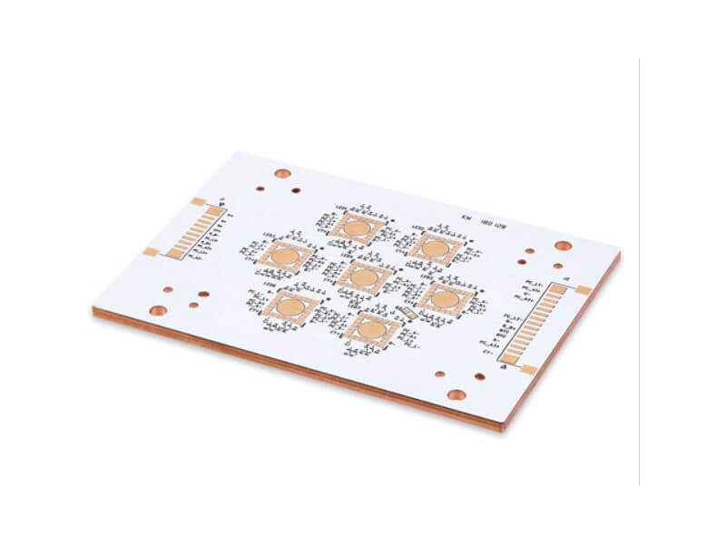
A breakaway tab is the small piece of laminate left between the board and the frame to hold the board during assembly. The tab is cut by the router, together with a line of small holes that perforate it, so that the board can be broken free later. The holes concentrate the stress and set the break line, and the tab itself should be placed so that the break does not pass near a component, a connector or a trace that has to survive.
Tab placement is a mechanical problem with an electrical consequence. A tab should be at a point where the board is stiff and where the break will not lift a pad, and the tab should be wide enough to hold the board but narrow enough to break by hand. Two or three tabs per small board and four or more on a large one is typical, and the choice is made with the depanelization method in mind rather than on its own.
<img src="https://www.gopcba.com/wp-content/uploads/2026/05/G9.jpg" alt="V-score grooves cut along a panel break line” />
Scoring And Its Limits
A V-score is a pair of grooves cut along the top and bottom of the panel on the same line, leaving a thin web of laminate to be broken. The technique uses no panel space for tabs, so the board count per panel is higher, and the separated edge is clean and straight on a rectangular board. It requires the board outline to be a straight line without cutouts or castellations, and it leaves a small bevel on the edge.
Scoring sets requirements on thickness and on the remaining web. A thick panel needs a deeper groove to break by hand, which weakens the assembly and may crack during handling, while a thin panel may break in the machine. The depth is normally controlled so that roughly one third of the thickness remains, and the tolerance on the score position belongs on the panel drawing together with the board outline.
Design Rules Around The Panel
Everything the assembly line needs is placed in the frame rather than on the boards. Fiducials for the printer and the placer, tooling holes for the machine pins, a test coupon for impedance and a process coupon for solderability all live in the rails or in the waste area between boards. The rules for that geometry are set out under board outline and mounting design and PCB slot and edge routing rules.
Components also have to stay away from the edges. A part placed within a few millimetres of a break line will be stressed when the board is separated and may crack, and a connector that overhangs the edge can interfere with the rail. The clearance that placement needs around each part is the courtyard, and it is discussed under placement order and pad positioning.
How The Boards Are Separated
Hand breaking is the cheapest method and the least controlled. The board is bent until the tabs break, and the stress travels through the laminate and through any component near the tab. It is acceptable for a board with no ceramic parts near the break line and unacceptable for one with chip capacitors in the corners.
A cutter or a nibbler removes the tab material rather than breaking it, which is cleaner but slower and produces dust. A router follows the outline with a small cutter and leaves the best edge, at the cost of a fixture and of the time to load and unload each board. A laser removes the tab by ablation and is used for thin and flexible materials. Whichever method is chosen, the panel should be supported underneath, because a board that is unsupported during separation bends and that bend is what cracks the components.
Process Control and Verification
On a design of this kind, panel size is the item that decides how the rest of the board is arranged. Documenting the assumption is part of the design work, and a short note on the drawing prevents a question that would otherwise arrive a day later and cost a day of schedule. The process window is set by the narrowest step in the flow, so an improvement anywhere else shows up as margin rather than as yield until that step is addressed.
Panel Drawing And What It Must Show
The panel drawing is a real drawing, not a note. It shows the panel outline and its tolerance, the position of every board within it, the rail width, the tooling holes and fiducials with their coordinates, the tab positions and widths, the score lines where they are used, and the direction of the material weave. It also states the break method, because a panel that is designed for a router may not survive hand breaking and a panel that is designed to be snapped by hand needs the tabs placed accordingly.
Two items are usually forgotten and both cause trouble. The first is the orientation of the boards, since a panel that mixes orientations makes the stencil and the placement program more complicated than they need to be. The second is the marking, because a board that carries a reworkable barcode or a date code position needs that position to be in the same place on every board rather than at the convenience of the panel layout.
FAQ
How much space should be left between boards on a panel? Enough for the cutter and for the material that the separation method needs, typically 2 to 5 millimetres for routing and a wider gap where the tab has to be sawn away.
Can a panel be scored and have tabs at the same time? It can, but the combination is rarely worth the trouble, because the score already defines a straight break line and the tabs would add constraints without adding stiffness.
Who decides the panel layout? It is usually proposed by the fabrication shop and approved by the designer, since the shop knows the equipment and the designer knows which parts are sensitive to the stress of separation.