PCB Quality Control: Test Methods on the Production Floor
Every process step can introduce a defect, and the defects look different depending on where they were created. That is the fundamental reason PCB quality control cannot rest on a single method. A board that passes one test may still carry a fault that only becomes visible under a different technique, and the practical approach is to combine methods so that each covers what the others miss.
Why One Test Is Never Enough
Consider what a single technique can see. Continuity testing detects a broken or bridged conductor, but cannot judge a marginal joint. Optical inspection finds missing and misplaced components, but cannot see beneath a package body. Functional testing confirms that the assembly works, but only under the conditions applied, and it rarely identifies where a marginal defect sits.
The consequence is that each method answers a different question, and a programme that uses only one of them leaves a predictable blind spot. The useful objective is not maximum testing but appropriately distributed testing, placed where defects are created and where detection is cheapest.
Automated Test Systems and Instrumentation
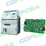
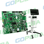
Modern automatic test equipment is built around the idea that a computer can replace much of the instrument rack. Specialised software performs the functions that an oscilloscope, a signal generator and a data acquisition unit would otherwise provide, together with the mathematical processing of the captured measurements.
The advantage is size and cost. A test system built on this principle occupies less space than the equivalent bench of instruments, costs less to develop and can be updated by changing software rather than hardware. Because the measurement chain is largely digital, results are recorded, repeatable and available for statistical analysis, which is what turns testing from a gate into a process control tool.
Continuity Testing: Opens and Shorts
Continuity testing, sometimes called bare board testing, verifies that every net that should be connected is connected and that no two nets are bridged. The board is held on a fixture that contacts each net, and the system measures resistance between the expected pairs and isolation between everything else.
On a bare board the test is unambiguous, because there are no components to confuse the result. The fixture is the main engineering effort: it must contact every net, accommodate the board outline and the mounting features, and apply pressure evenly so that no contact is marginal. Test point design in the layout therefore matters, since a net without an accessible point cannot be probed. The principles of production inspection are covered in PCB quality inspection.
In-Circuit Test and Component Verification
After assembly, in-circuit test applies stimulus through a bed of nails fixture and measures the response at each node. The testing software issues a digital signal, which is converted to an analogue stimulus, routed through a switching matrix under processor control and applied to the board at the intended position. The measured analogue response is converted back to digital form and evaluated by the software, which decides whether the board passes.
Because each node is measured individually, the technique identifies what is present and what is not: a missing component, a wrong value, an open joint, a short, or a device that fails to respond. That specificity is its main value, because a fault located precisely can be repaired quickly. The limitation is that it verifies behaviour under test conditions rather than in service, so a joint that fails only when warm will pass. Its role in the wider inspection sequence is described in SMT inspection methods.
Functional and Edge Testing
Functional testing operates the assembly as a whole, applying the inputs the product would receive and confirming that the outputs are correct. It is the closest approach to the customer experience and therefore catches integration faults that node-by-node testing cannot, such as timing interactions between devices or a firmware configuration error.
Edge testing concentrates on the boundary of the board, verifying the connector and interface behaviour where the assembly meets the outside world. Because interface pins are the most exposed part of the design, both electrically and mechanically, this check catches damage and contamination that internal testing would miss.
Optical and X-Ray Inspection
Optical inspection compares the assembly against a reference or a set of rules, confirming presence, absence, polarity, orientation and the visible shape of solder fillets. It is fast, it can be placed at several points in the line, and it is most valuable when positioned as early as possible so that faults are corrected rather than accumulated.

X-ray inspection handles what optics cannot. It images the joints beneath area array packages and other concealed locations, revealing bridging, voids and joints that are too large or too small. It is mandatory for ball grid array assembly in any product where reliability matters, and the acceptance criteria should be agreed with the customer rather than decided by the operator. Related requirements appear in PCB quality control and the broader assembly sequence in SMT process window capability.
Combining Methods into a Flow
A workable programme layers the methods. Incoming material is checked before it enters the line. Bare boards are continuity tested. After assembly, optical inspection finds placement and solder defects, in-circuit test verifies components and connections, X-ray confirms the concealed joints, and functional test confirms the product works as a system.
The combination suited to small and medium volumes is often narrower, and manual visual inspection still plays a role at the final stage. What matters is that the coverage is deliberate, that the acceptance criteria are defined, and that every result is recorded so that recurring defects can be traced back to the process that produced them rather than merely screened out.
Sampling, Data Feedback and Traceability
Not every board can receive the slowest available test, so production floors use sampling plans keyed to how critical the product is. A consumer gadget may ship on continuity plus a spot check, while a medical or automotive assembly earns full in-circuit and functional coverage on every unit. Sampling rates should be written down, reviewed whenever field returns appear, and tightened after any process change, because a rate that was defensible on a mature line is not necessarily defensible on a line that has just switched paste, laminate or solder alloy. The plan is a living document rather than a formality signed once at launch.
Data feedback closes the loop. Failures should be logged with board serial number, test step, fixture and operator so that trends become visible before scrap volume explodes. A rise in the resistance of one net points at a plating bath or an etch line; a cluster of the same component failing in-circuit points at placement or reflow. Serial numbers and lot codes also give traceability, which matters when a customer reports a failure months later and the question becomes which revision and which panel the board came from. Without that recorded data, every defect stays a surprise that has to be investigated from scratch.
FAQ
What is the difference between continuity and in-circuit test? Continuity testing checks connectivity on a bare board, before components are fitted. In-circuit test measures nodes on an assembled board to confirm components and joints.
Can functional test replace in-circuit test? No. Functional test confirms the product works but rarely identifies which joint or component is responsible when it does not. In-circuit test exists to locate the fault precisely.
When is X-ray testing essential? Whenever joints are concealed, which in practice means ball grid array and similar area array packages. Optical inspection cannot see underneath them, so X-ray is the only direct check available.