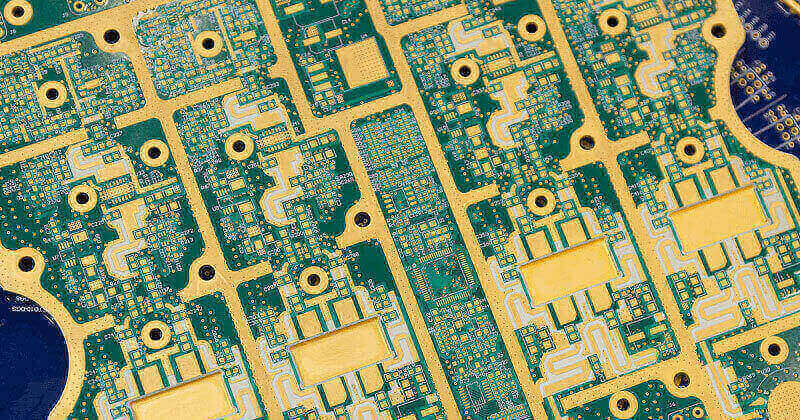
Selective Soldering Process Control
Selective soldering fills the gap between reflow and hand soldering. It is used where a board carries a small number of through hole parts that cannot survive a reflow oven, or where the thermal mass of a connector makes a wave impractical. The process is slower than wave soldering by design, and its quality depends on the way a narrow set of parameters is controlled rather than on the machine alone.
Where the Process Fits
A mixed technology board usually carries most of its components in reflow and a handful of through hole parts that are added afterwards. Those parts may be connectors with a large thermal mass, parts with a body that cannot tolerate reflow temperatures, or parts that must be replaced in the field and therefore need a robust joint.
Hand soldering can do the same job, but it depends on the operator, it is slow, and the result varies between shifts. Selective soldering replaces that variability with a programmable machine, at the cost of a fixture and a program that must be developed and maintained.
The decision is usually economic once the volume passes a threshold. Below that threshold a skilled operator is cheaper, and the choice should be made on the volume, the number of joints per board and the repeatability the product actually requires.
Flux Application
Flux is applied to the joints only, and the method determines both the quantity and the placement. Spray fluxing with a moving head gives the finest control, drip or drop jetting gives a repeatable deposit with less overspray, and the older methods of brushing or foaming are rarely used on modern machines.
Nozzle diameter and spray time set the quantity, and it should be measured by weight on a sample board rather than judged by appearance. Too little flux gives incomplete wetting and a rough joint, while too much leaves residue that must be removed and can produce voids during soldering.
Flux deposition must be aligned with the nozzle position. A small offset means the flux lands beside the hole rather than in it, and the symptom is a joint that wets on one side only. Alignment should be checked whenever the fixture is changed or the program is edited.

Preheat and Thermal Balance
Preheating is applied from below, from above, or from both directions, and its purpose is to bring the assembly close to soldering temperature before the wave arrives. A board that enters cold forces the nozzle to supply all the energy, which slows the process and produces incomplete fill.
Temperature should be measured on the board rather than on the heater. The relevant reading is the top side temperature at the joint, and it must be taken with the fixture in place because the fixture itself absorbs and reflects heat. The thermal mass of a connector body can delay the joint temperature by tens of seconds.
Insufficient preheat shows as poor fill and as cold joints on the parts with the largest mass, while excessive preheat damages parts and oxidises the flux. The set point is a compromise for the board, and a board with widely different masses may need a second program rather than a single average setting.
Nozzle and Wave
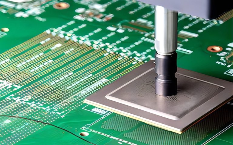
The nozzle diameter is matched to the joint. A nozzle narrower than the hole gives a weak flow that cannot fill the barrel, while an oversized nozzle floods neighbouring features and produces bridges. For a connector with several pins in a row, the choice is between a single small nozzle applied pin by pin and a multi hole nozzle applied to the whole row.
Dwell time is the time the nozzle stays over the joint, and it controls the heat transferred as much as the solder supplied. A short dwell gives a cold or partially filled joint, while a long dwell heats the board and increases the risk of damage and of intermetallic growth. The window is narrower than in wave soldering because the energy source is local.
Solder temperature and nozzle height complete the set. The nozzle should be close enough that the wave contacts the joint without touching the body, and the height must be measured rather than assumed because the fixture sets it. Nozzle condition matters: an eroded or partially blocked nozzle produces a defect that no parameter change can correct.
Fixturing
The fixture holds the board, masks the areas that must not receive solder and provides the reference for the program. It is the part of the process that is most often underestimated, and most of the defects that appear after a program change can be traced to it.
Material choice matters because the fixture sits in the heat. A resin or a composite that deforms will change the board position, and the change is progressive, so the process drifts over a shift rather than failing at once. Metal fixtures with insulating inserts are common where the geometry allows them.
Masking of adjacent features is part of the fixture design. Solder must be kept off gold fingers, off press fit pins and off parts that cannot tolerate the heat, and the mask should be checked for wear at intervals because a worn mask allows solder where it is not wanted.
Defects and Their Causes
Incomplete fill appears when the flux is insufficient, the preheat is low or the dwell is short. Where it affects only the pins at one end of a connector, the fixture is likely to be tilting the board so that the nozzle is further from the joint on that side.
Bridging between adjacent pins comes from an oversized nozzle, excessive solder, worn masking or a board that has not been cleaned with enough flux activity. Where the pitch is fine, the gap between pins is small and the process window narrows accordingly, which is why fine pitch work is usually handed to a different process.
Solder balls and spatter come from excessive flux, from moisture in the board and from a nozzle that is too far from the joint. They matter because they can remain on the assembly and cause a short after conformal coating, so the inspection after selective soldering should always follow cleaning.
Programs, Verification and Records
Every product should have a program with the nozzle type, the flux quantity, the preheat temperature, the dwell times and the fixture reference recorded together. When a defect appears, the record allows the change to be found quickly instead of re-establishing the process from scratch.
Verification should include a visual check on the first board of a run, a sectioned sample at intervals to confirm barrel fill, and a check of the nozzle condition. The section is the only way to confirm fill inside the barrel, because a joint can look good from above while the barrel is only partly wetted.
The records should feed into the build documentation alongside the defect data and the prototype history, so that a recurring problem is recognised as a pattern rather than treated as a new fault each time.
FAQ
When is selective soldering better than hand soldering? Once the volume and the joint count justify a fixture and a program. Below that threshold a skilled operator is usually cheaper.
What controls the fill in a selective solder joint? Flux quantity, preheat, dwell time and nozzle position. A short dwell or a low preheat leaves the barrel only partly filled.
Why does the fixture matter so much? It sets the board position and the masking. A fixture that deforms changes nozzle distance progressively, so the process drifts during a shift.