Thermal Imaging for Board Bring-Up
Why Heat Tells the Story
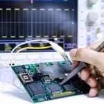
Every electrical fault leaves a thermal signature. A shorted device draws current and gets hot, a high resistance joint dissipates power, a component that is marginally rated runs warmer than its neighbours, and a reverse polarity part can be found by its temperature before any voltage measurement is taken. A thermal camera turns those signatures into a picture, which makes it one of the fastest tools in a bring-up kit. The instrument does not replace the oscilloscope, but it often tells you where to put the probe.
What an Infrared Camera Shows
An infrared camera measures radiated energy and converts it to a temperature map, with a resolution set by the detector and the lens. What it shows is the surface temperature of what it can see, which for a populated board means the packages, the solder joints and the board itself. The reading is affected by the surface emissivity, so a shiny metal surface reads lower than it is and a black plastic package reads close to the truth; a thin coat of matte paint or a piece of electrical tape can make a measurement comparable. Absolute accuracy matters less than the contrast, because the useful information is which area is warmer than its surroundings.
Finding a Short Before Powering Up
The classic use is the hunt for a short on a rail. Rather than injecting current into the whole board and hoping, a current limited supply is set to a low voltage and a modest current, and the thermal image shows the path: the shorted device or the region of the plane gets warm first, and the warm trail often reveals whether the current is flowing to a specific part or spread across a plane. With a short on a large plane, a sensitive camera can sometimes see the gradient that leads to the fault. The technique requires the current to be limited so that nothing is damaged while the board is being diagnosed.
Spotting Marginal and Reverse Parts
A board that works but runs hot is a board with a marginal design. Thermal imaging shows which device reaches the highest temperature and whether that temperature is concentrated in one place or distributed. A capacitor that runs much hotter than its neighbours may be a reversed electrolytic, a resistor that is warm may be dissipating far more than its share, and a regulator that is hot under light load may be oscillating. Comparing a known-good board against a suspect one, side by side and under the same conditions, makes those differences obvious in a way that a single measurement rarely does.
Method and Common Mistakes
The mistakes are consistent. Powering a board from a supply with no current limit turns a diagnosis into a demolition. Measuring through a plastic enclosure or a coating gives a temperature that is lower and slower than the junction. Taking a single snapshot ignores the fact that most faults develop over time, so a short video of the warm-up is more informative than one frame. Ignoring the ambient and the air flow leads to false conclusions, because a board in still air and a board under a fan are not comparable. And reading a shiny connector as cool, without accounting for its emissivity, is a classic error.
Bring-Up Sequence
A disciplined bring-up uses the camera as one of several checks in a fixed order. The board is inspected visually first, then the supply impedance is measured on each rail, then power is applied with the current limited and the thermal image is captured immediately and over the first minutes. The rails are checked for voltage and ripple, and the clock and reset are verified before any signal work begins. The thermal image taken at this stage is the baseline; a later image, after the board has run under load, is compared against it. Differences between the two are often the first sign of a problem that the scope has not yet shown.
Catching Reliability Problems Early
Beyond bring-up, thermal imaging is a screening tool for the problems that would otherwise appear in the field. A connector that heats under load indicates a contact resistance that will worsen; a trace that runs warm suggests a current density that is higher than the design intended; a component that cycles in temperature as the load changes suggests a thermal path that is inadequate. Where the product has a thermal requirement, imaging the assembly under the worst case load, and doing it again after the coating and the enclosure are in place, is the test that confirms the thermal design rather than the bench behaviour.
Choosing and Reading the Instrument
A camera for board work needs enough resolution to separate a small package from its neighbour, a focus range that works close to the board and a frame rate that captures change rather than averages it. The display matters as much as the sensor: a reading taken over a wide range hides the small differences that reveal a fault, so the span should be narrowed to the region of interest. Locking the colour scale between two images is what makes a comparison valid, because an auto scaled image of a warmer board will look the same as an auto scaled image of a cooler one.

FAQ
What does thermal imaging find? Shorts, high resistance joints, reversed or marginal components and thermal design problems, all from their heat signature.
Can it find a short without powering the board? No; it needs current. The safe method is a current limited supply at low voltage, so the fault warms without damage.
Why is the reading not the true temperature? Emissivity varies by surface, and a shiny metal reads low; a matte coating or tape makes the reading comparable.
Is one image enough? No. Recording the warm-up over time shows faults that develop, and comparing against a known-good board is far more useful.
Where else is it useful? Under load and after coating or enclosure, it verifies the thermal design rather than only the bench behaviour.
Conclusion
Thermal imaging turns an invisible fault into a visible one, and it does so in seconds, which is why it belongs in the first minutes of a bring-up. Limit the current, record the warm-up and compare against a good board. Bench verification sits with PCBA testing, the assembly being probed comes from PCB assembly, and the thermal path is fixed by PCB design and layout. First power-up of a new design is a normal step in prototype PCB assembly in 2026.