PCB Antenna Design: Sizing, Ground And Tuning
An antenna printed directly on a circuit board looks like a simple piece of copper, and behaves like something far less predictable. Its performance depends on the board it is printed on, on what surrounds it in the finished product, and on how well it is matched to the feed. Two identical layouts on boards of different sizes will not radiate the same way.
This article covers the design parameters that matter, the measurements that describe them, and why a practical antenna always ends up being tuned on the real assembly.
The subject has a reputation for being obscure, which is partly deserved. The physics is well understood, but the variables are numerous and they interact, so the work is empirical even when it is informed.
An Antenna Is Half Of A System
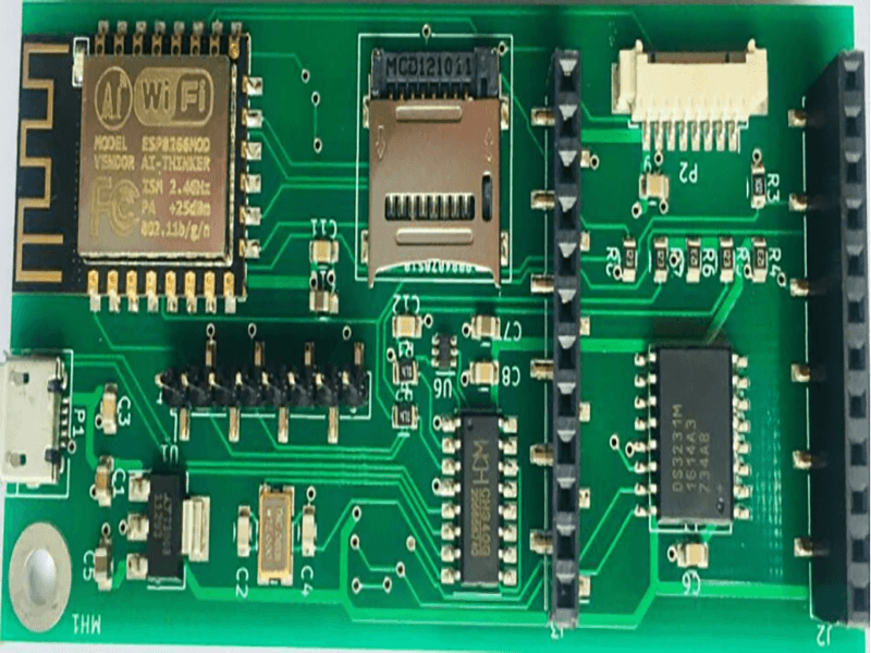
The radiating element is only one part of the antenna. The other part is the ground plane it works against, and on a small board the ground plane is usually the dominant contributor to the radiation. That is why a compact antenna specified for one board size does not perform the same way on a board half the size, and why suppliers ask for the dimensions of the board before recommending a part.
The consequence for the design is that the antenna has to be considered together with the layout around it. The area beneath and beside the element, the position of the feed, and the presence of a battery, a display or a metal enclosure all change the tuning. A layout that reserves clearance for the antenna and keeps the ground plane definition under control gives the designer something to tune; one that treats the antenna as a component to be dropped in does not.
The Three Figures That Describe It
Three quantities describe the performance of an antenna in practice. VSWR, the voltage standing wave ratio, describes how well the element is matched to the feed line over the operating band, and a value close to one means most of the power is being accepted. Gain describes how the radiated power is concentrated relative to an ideal radiator in a given direction, and it is frequency dependent. Efficiency describes how much of the power that reaches the antenna is radiated rather than lost as heat in the conductor and the dielectric.
The three are linked, and they cannot all be maximised at once on a small board or within a small product enclosure. A very narrow structure can be well matched over a narrow band, and a wider structure can cover more spectrum at the cost of some gain. The bandwidth is the fourth figure that always enters the discussion, because a product has to cover a range of frequencies rather than a single point.
Ground Plane And Board Size
Designing the ground plane is as important as drawing the element. The plane has to be continuous under the circuit and defined in the region the antenna works against, without being so close to the element that it detunes it. A plane that is cut by slots, or that is broken into islands, changes the behaviour in ways that are difficult to predict.
The mechanical outline is part of the same decision, since the ground plane cannot be larger than the board. Increasing the board size generally improves the bandwidth and the efficiency at low frequencies, which is one reason a physically small product finds it harder to meet a low band specification, and the metal content of the enclosure has an effect of its own that is best measured rather than predicted. Routing the feed and keeping the transmission line structure consistent from the radio to the element is the other half of the job.

Matching And The Feed
The feed has to present fifty ohms to the radio module, and the element has to be transformed to that value across the band. The transformation is usually done with a small matching network beside the feed point, using a few reactive components in a configuration that can be adjusted after measurement. The layout should allow for that adjustment, with pads that can be changed without reworking the board.
The feed line itself is a controlled impedance trace, and it should be treated as one, with a continuous reference beneath it and as few discontinuities as possible. A feed that changes layers, or that runs for a long distance, adds loss and reflection before the signal has reached the antenna. Where a layer transition is unavoidable, the rules for vias in a controlled impedance path apply.
Keep Out And Placement In The Product
The keep out region under and around the antenna belongs on the layout drawing, and it has to survive the mechanical design. Copper, a battery, a speaker, a metal screw or a conductive coating on the inside of the enclosure will all shift the tuning, and most of them will reduce the efficiency. Placing the antenna at the edge of the board, away from the power supply and away from anything that switches, keeps it clear of the largest sources of interference.
The interaction runs in both directions as well. An antenna that couples into the rest of the circuit can raise the noise floor, so the same discipline that governs the suppression of emissions on the board applies to the positioning of the radiating element. Planning the antenna and the rest of the layout together, early, is what avoids a redesign at the end.
Tuning And Measurement
An antenna is measured with the board in the state it will be in service, or as close to it as possible. A vector network analyser measures VSWR or return loss across the band, which confirms the match but not the radiation pattern. Efficiency and gain require a chamber and a known reference, which is why most designs use measured pattern data from the supplier as a starting point and then tune the match on the actual board.
The practical sequence is to build the board with a matching network that can be adjusted, measure the match, change the components, and repeat until the band is covered. Any change to the enclosure or the mechanical arrangement invalidates the result and requires another pass. That is why the tuning is performed last, on the real assembly, and why the ability to change a component value is worth designing in. gopcb builds boards with controlled impedance feeds and defined keep out regions, and confirms the feed geometry against the stackup so that the antenna starts from the impedance the design assumes.
Process Control and Verification
On a design of this kind, bandwidth is the item that decides how the rest of the board is arranged. Running a first article through the same checks as the production panel confirms that the two agree, and that comparison is the cheapest form of process control available at prototype stage. Keeping a sample from the panel turns a dispute into a measurement, because the same coupon can be re-examined by both parties without rebuilding the batch.
FAQ
Can an antenna be designed entirely in simulation? A simulation gives a good starting point, but the enclosure, the battery and the board size all shift the result. Tuning on the real assembly is the norm.
Why does the same antenna perform differently on two boards? Because the ground plane it works against is part of the antenna. A different board size means a different radiator.
Does a lower VSWR guarantee better range? Not on its own. The match describes how much power is accepted; the gain and the efficiency decide how much of it is radiated where it is needed.