PCBA Prototyping: How a Quick-Turn Service Works Step by Step
PCBA prototyping compresses the normal board and assembly flow into days rather than weeks, but it does not skip steps. Understanding the sequence helps a design team prepare the right data, avoid the delays that come from incomplete files, and interpret what the returned boards actually prove.
A quick-turn service still fabricates the board, sources the components, assembles the board and inspects it. What changes is queue priority, panel sharing and a strong emphasis on getting the data package right the first time.
Step One: Submitting the Design Data
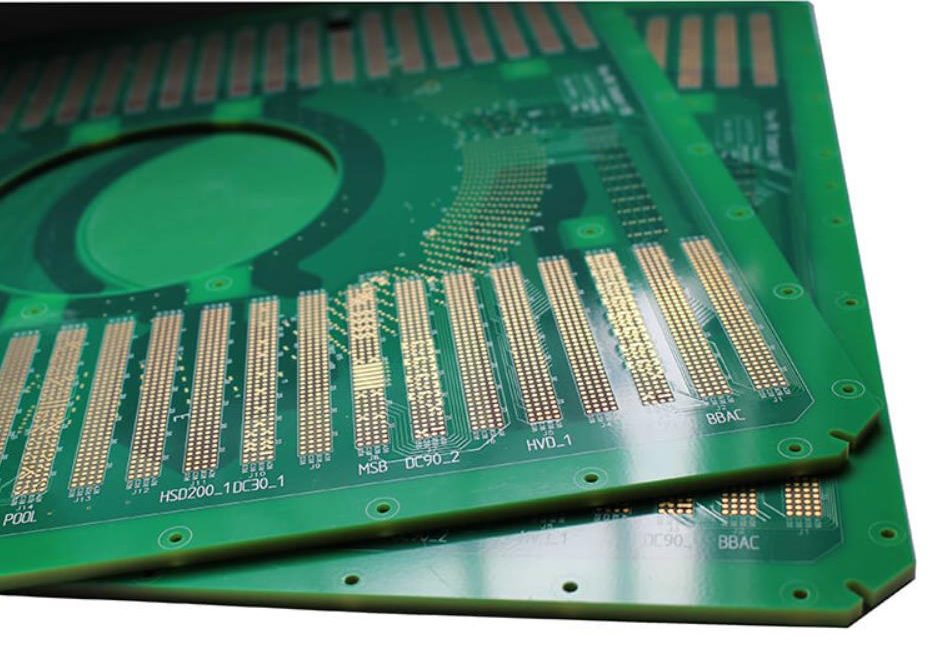
The process starts with a data package. It contains the Gerber files describing each copper layer, solder mask and silkscreen, the drill file, the bill of materials with manufacturer part numbers, and the pick and place file listing component positions and rotations.
Two more items are often overlooked. The fabrication drawing states material, thickness, copper weight, surface finish and impedance requirements, and the assembly drawing states which side is populated, the panelization scheme and any special instructions. A missing assembly drawing is a common cause of a board arriving populated on the wrong side.
Data review happens before anything is built. The service checks that the drill file matches the copper, that the outline is closed, that aperture sizes are manufacturable and that the bill of materials is complete with quantities and reference designators.
Step Two: Gerber and BOM Review
Gerber files define geometry but not intent. A review compares them against the design rules the fabricator can hold and flags anything marginal, such as a trace narrower than the process allows or a solder mask sliver that will lift.
The bill of materials review is about availability. Parts that are obsolete, out of stock or supplied in a reel the placement machine cannot use will delay a quick-turn build, and substitutes must be approved by the designer rather than chosen silently.
This is the point where a design can still be changed cheaply. Once fabrication starts, the only remaining flexibility is in component substitution, and even that is limited.
Step Three: Quick-Turn Fabrication
Fabrication follows the standard sequence at higher priority: inner layer imaging and etching for multilayer boards, lamination, drilling, plating, outer layer imaging, etching, solder mask, surface finish and routing. Quick-turn work often shares a panel with other jobs, which is why unusual board thickness or a non-standard copper weight can slow it down.
For a simple two-layer board, the sequence may complete in a day. A four-layer board with impedance control takes longer because the stackup must be built and coupons measured. Requesting impedance control on a prototype is worthwhile when the final product needs it, because the geometry can then be validated on the prototype rather than at production.

Step Four: Component Sourcing and Kitting
Assembly requires every part on hand before the line is set up. Kitting collects the reels and trays, verifies quantities against the bill of materials, and checks that each part matches its footprint. Moisture-sensitive parts are baked and dry-packed as required.
Much of the delay in a quick-turn build happens here rather than in fabrication. A single missing part can hold an entire build, so designing with commonly stocked packages and avoiding single-source parts shortens the cycle noticeably.
Step Five: Assembly
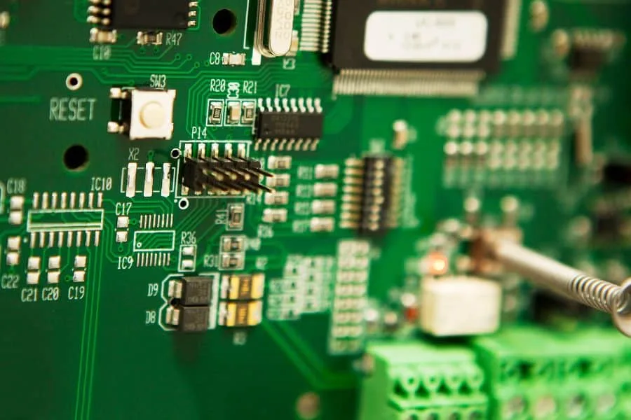
Assembly runs through solder paste printing, placement and reflow, using the same equipment as production work. Prototype runs are often grouped with other jobs to fill a panel, which is why the pick and place data must be accurate and the panelization must suit the machine.
Through-hole parts are added after the SMT reflow, by hand or by selective soldering. Connectors, switches and large capacitors usually fall into this category, and their positions affect both the fixture and the assembly sequence.
Step Six: Inspection and First Article
The first assembled board is inspected in detail. First article inspection compares the placed parts, their orientation and their solder joints against the assembly drawing and the bill of materials. Automated optical inspection covers every board; X-ray is used where ball grid arrays or hidden joints are present.
The results are reported, not just recorded. A prototype that passes inspection but has three parts placed by hand after reflow is telling the design team something about the layout, and that information is as valuable as the electrical test result.
Step Seven: Test and Feedback
Functional test closes the loop. The board is powered in a controlled sequence, brought up block by block, and measured against the requirements the prototype was built to answer. Test points designed into the layout make this stage a measurement exercise rather than a probing exercise.
The output of a prototyping cycle is not only a working board but a list of changes. Capturing those changes while the measurements are fresh, and folding them into the next revision, is what keeps the number of iterations low before the design moves into production.
The wider path from prototype to production is covered in PCBA development process, layout choices that speed assembly are described under placement order and pad positioning, and fabrication limits are collected in design guidelines for manufacturable boards.
What Determines the Turnaround Time
Turnaround is set by the slowest step, and that is rarely fabrication. A two-layer board can be etched quickly, but the build still waits for components. Parts held in stock locally shorten the cycle; parts ordered from a distributor with a week of lead time define it.
Panel utilization also matters. A small board shares a panel with other jobs and moves quickly, while an unusual size, thickness or copper weight may need its own panel and therefore its own slot in the schedule.
Finally, data quality drives the clock. Incomplete Gerber layers, a bill of materials without manufacturer part numbers or a missing assembly drawing each trigger a query, and every query costs time that no priority fee can recover.
How to Prepare for a Fast Build
Freeze the design before submitting it. A prototype built from a moving schematic produces a board that answers no question cleanly, because two changes made in the same revision cannot be evaluated separately.
Include test points, keep the reference designators visible in the silkscreen and state the assembly side explicitly. These three details prevent the most common rework on prototype assemblies and cost nothing during layout.
Keep a record of what each build was meant to prove, so that the next revision is based on the answer rather than on an impression of it.
FAQ
What is the minimum data set for a quick-turn build? Gerber files, a drill file, a bill of materials with part numbers, a pick and place file and an assembly drawing. Missing any one of them usually produces a question that stops the build until it is answered.
Can I change the design after submitting it? Only before fabrication starts, and a change usually resets the queue position. Reviewing the data package thoroughly before submission is faster than amending it afterward.
Is a prototype board assembled like a production board? Yes, with the same printing, placement and reflow processes. The difference is quantity and priority, not method, which is what makes prototype results representative of production behavior.