Peak Detector Circuit Design
A peak detector follows a signal upwards and holds the highest value it has reached. It is used to measure an amplitude, to capture a transient and to drive an automatic gain control, and its accuracy depends on how the diode drop and the droop are handled.
The Simple Diode Detector
A diode in series with a capacitor charges the capacitor to the peak of the input less the forward drop of the diode. The capacitor holds the value until something discharges it.
The forward drop is the fundamental error, and it varies with the current and with temperature. A silicon diode drops around seven tenths of a volt at a modest current, which is large compared with a signal of a few volts.
The detector also loads the source asymmetrically. During the charging phase the source sees a low impedance, and during the hold it sees the reverse leakage of the diode and the capacitor. That asymmetry is what makes the simple circuit unsuitable for a precision measurement.
The Precision op amp rectifier
Putting the diode inside the feedback loop of an operational amplifier removes the effect of the forward drop. The amplifier supplies whatever voltage is needed to make the diode conduct, and the output follows the input within the offset of the amplifier.
The arrangement is a precision half wave rectifier, and it is the basis of almost every accurate peak detector. The amplifier has to be able to swing far enough to overcome the diode drop, and it must recover quickly when the input falls below the held value.
An amplifier with a limited output swing does not charge the capacitor to the full peak, and the error appears as a gain error at high levels. A rail to rail output stage or a slightly higher supply avoids it.
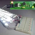
<img src="https://www.gopcba.com/wp-content/uploads/2026/05/smart-home-PCBA.jpg" alt="Peak detector circuit with a hold capacitor on a measurement board” />
The hold capacitor and droop
The hold capacitor stores the peak, and its value sets the acquisition and the droop together. A large capacitor holds longer and charges more slowly, so the value follows from the fastest event to be captured and the longest hold time required.
droop is the discharge of the capacitor through the reverse leakage of the diode, the input bias current of the amplifier and the leakage of the capacitor itself. A film capacitor has a much lower leakage than a ceramic with a high dielectric constant.
The amplifier used to buffer the held value must have a low bias current, because that current flows out of the capacitor continuously. A part with a bias current of a picoamp gives a droop of a microvolt per second into a capacitor of one microfarad.
The reset switch
A reset switch discharges the capacitor before the next measurement. It can be a transistor, a junction field effect transistor or an analog switch, and its own leakage adds to the droop while it is open.
The switch resistance and the capacitor form a time constant for the reset, which sets the minimum interval between measurements. A switch with a few tens of ohms and a capacitor of a microfarad gives a reset time of tens of microseconds.
The charge injection of the switch appears as a small step in the held value after the reset. Where the peak is small compared with the supply, that step is a significant fraction of the measurement.

Tracking and Reset Behaviour
A detector that is reset by the signal itself, when the input falls below the held value, is called a tracking detector. It follows the envelope of a waveform rather than the absolute peak.
The discharge path is a resistor from the hold node to ground or to the input, and its value sets the discharge rate together with the capacitor. The combination is a compromise between following a fast envelope and holding a slow one.
A sample and hold arrangement with a controlled reset gives a defined measurement window and a repeatable result. It costs a switch and a timing signal, and it removes the dependence on the signal shape.
Speed and Bandwidth Limits
The loop bandwidth of the amplifier sets how fast the circuit can follow a rising edge. A fast peak needs a wide bandwidth amplifier and a small capacitor, at the cost of a higher droop.
The slew rate of the amplifier also limits the charging of the capacitor, because the capacitor current is supplied by the amplifier output. A large capacitor cannot be charged quickly by an amplifier with a modest output current.
The diode recovery time matters at high frequencies as well. A slow diode keeps conducting briefly after the peak, and the capacitor is discharged a little through the reverse recovery, which appears as a droop that depends on the signal.
Noise and the Measurement
Noise on the input is captured along with the signal, and a peak detector responds to the noise peaks rather than to the average. That is the reason a reading taken from a peak detector is higher than the average of the same signal.
Filtering before the detector removes the broadband noise and the measurement then follows the signal envelope. The filter must not round the peak being measured, which is the trade between noise and accuracy.
For a repetitive waveform the measurement is stable and the filter can be slow. For a single event the filter is set from the rise time of the event, and the noise becomes a real limit on the accuracy.
Choosing the Components
The diode has to be fast and its reverse leakage low. A small signal Schottky diode is fast with a higher leakage, while a silicon small signal diode has less leakage and a larger forward drop that the feedback loop compensates.
The capacitor is a film type for a long hold and a ceramic for a short one. Its voltage coefficient and its dielectric absorption both affect the reading after a fast change in the held value.
The amplifier is chosen for its input bias current first and its bandwidth second. A part with a femtoamp bias current and a modest bandwidth suits a slow measurement far better than a fast part with nanoamps of bias current.
Verification and Faults
Verify the detector with a known square wave and measure both the held value and the droop over the required hold time. The square wave makes the peak unambiguous and the droop easy to see.
Check the reading at several amplitudes to separate a gain error from an offset. A detector with an unused amplifier swing shows a gain error that grows with the amplitude.
A reading that drifts downward over seconds is a droop problem, and one that reads high is capturing noise. The release checks that keep such a circuit consistent are collected in our PCB design release checklist, the assembly points in judging PCB quality, and the layout measures for a high impedance node in our guide to mixed signal board design.
FAQ
Why does my peak detector read low? The diode drop is not compensated, or the amplifier cannot swing far enough to charge the capacitor to the full peak.
How do I reduce the droop? Use a low leakage capacitor, an amplifier with a low bias current and a clean, well guarded board.
Why does the reading follow the noise? A peak detector responds to the highest excursion. Filter the input before the detector, or use a slower hold.