Placement Force on Thin Boards: Z Axis Control and Board Support
A placement head that presses a component into paste is applying a force through the board, and a thin board that is not supported underneath will bend. The bend is small, but it is enough to move a fine pitch device after the vision system has already measured where the pads were.
Why Force Matters More on a Thin Board
On a 1.6 mm board the stiffness is high enough that the placement force is absorbed by the laminate without measurable deflection. On a 0.6 mm board the same force produces a deflection that can exceed the placement tolerance, and the deflection depends on where the part sits relative to the supports.
The effect is not symmetrical: a part placed over a supported area is barely affected, while the same part placed halfway between two pins sees the largest movement. That is why support layout and placement force are set together, and why a placement accuracy figure quoted without them describes neither.
How the Machine Applies Force
The z axis brings the nozzle down until the component touches the paste, and the force that follows comes from the servo’s torque limit, from a spring in the nozzle holder or from a closed loop force sensor. Machines that detect contact electrically or by vacuum change stop as soon as the part lands, while others continue to a taught height and rely on compliance.
Contact detection is the more repeatable method on a thin board, because it stops the axis when the part meets the paste rather than at a position measured from a table. Where the machine uses a taught height, the board thickness and the support height are both inside the error budget.
Setting the Contact Height
The contact height is taught from the board surface, and on a thin board it is worth measuring the surface with the machine’s own vision or laser rather than trusting the nominal thickness. The paste height, the component termination and the nozzle tip all sit between the taught point and the pad.
Where the machine can measure the board before placement, the measurement is taken with the support already engaged, because a support pin that is set too low leaves the board lower than the measurement assumes. A support gap of more than a tenth of a millimetre is enough to move the result.
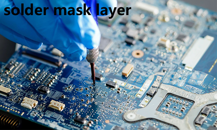
Force Values and What They Mean
Typical settings run from about 0.5 newtons for a small chip to 3 newtons for a large module, and a connector placed into a locating peg may need more. The figure is a setting on the machine, but what matters at the board is the pressure under the terminations, which depends on the area of the pads as much as on the force.
Too little force leaves a component sitting on top of the paste with no wetting contact at the terminations, and too much squeezes the paste out from under the pads and leaves the part standing on the mask. Both show up later as defects that look like paste problems rather than placement problems.
Board Support and Its Layout
Support is provided by pins, by a vacuum plate or by a dedicated fixture, and the pins are placed from the placement data rather than by eye. The aim is to have support within a defined distance of every placement position, commonly 25 mm, so that no component is placed over an unsupported span.
Magnetic pins on a steel table are the simplest system and the hardest to keep correct, because a pin that is knocked during a changeover leaves one area unsupported until a defect appears. The layout is usually recorded as a photograph or a drawing with the pin positions numbered, and it is checked at the start of each build.
Deformation and Its Consequences
The immediate consequence of deflection is placement offset, because the board moves after the vision measurement. A secondary consequence is mechanical damage, and a multilayer ceramic capacitor is the component most likely to show it as a crack that passes electrical test and fails later in thermal cycling.
Paste displacement is the third effect: a deflected board changes the gap between the stencil-printed deposit and the part, and paste that is pushed sideways can bridge to a neighbour. The three effects are often reported as three different problems, and they are all traceable to the same force and the same support.
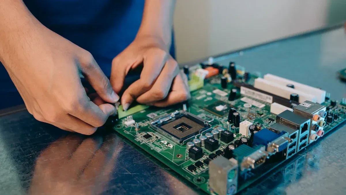
Nozzle Condition and Force Transfer
The nozzle tip is the point at which the force reaches the component, and a worn or contaminated tip changes both the pickup and the seating. A tip that is no longer flat rocks the component as it lands, which produces a tilt that no amount of force can correct.
Vacuum pickup interacts with the same variables, because a nozzle that is holding a part with too little vacuum releases it slightly late. The tip is inspected on a schedule and replaced on condition, and the vacuum level is checked against a gauge rather than by feel.
Monitoring and Verifying Force
Force is verified with a load cell placed on the table at the height of the board, which gives the actual force delivered by the head at the programmed setting. The measurement is repeated across the table, because a head that is level in one corner can be off in another.
A simpler production check is a paste displacement coupon: place a row of chips at the setting in use and measure the spread of the deposits under a microscope. The coupon does not give a force in newtons, but it shows a change in the same direction, which is what a shift check needs.
Documentation and Process Control
The record for a build should carry the force setting per component type, the support pin layout, the contact method and the measured board thickness. A change to any of them is a change to the placement process, even when the programme is untouched.
Where a product is moved between machines, the support layout and the force setting travel with it rather than being re-derived, and the first article confirms that the new machine reproduces the deposits seen on the old one. Our warpage control and paste volume notes describe how the board’s flatness and the deposit are measured as part of the same study.
FAQ
Can force be reduced to zero on a thin board? Not usefully, because some force is needed to seat the terminations in the paste. The answer is support under the placement position and a force low enough to avoid squeezing the deposit out.
Does the support pin height need to be set with a gauge? It does on a thin board. Pins are set to the board thickness with a gauge or a feeler rather than by eye, because the difference between a pin that is level and one that is a tenth of a millimetre low is invisible until the placement offset appears.
Why does the same programme place differently on a different board thickness? Because the contact height, the support height and the board stiffness all change together, and the machine has no way to know unless the surface is measured. The programme is therefore mated to the board it was taught on.