Press-Fit Pin Insertion Force and Plated Hole Control
A press-fit joint replaces solder with mechanical interference, and the whole connection depends on dimensions that are measured in tens of micrometres. The compliant pin must deform enough to grip the barrel, the plated through hole must be tight enough to hold it, and the insertion force must stay inside a narrow band that neither damages the barrel nor leaves the pin loose. This guide explains how gopcb balances those requirements in high layer count backplanes and daughter cards.
What Makes a Press-Fit Joint Work
A press-fit joint works because a metal pin is forced into a hole that is slightly too small for it. The pin compresses, the barrel stretches within its elastic range, and the contact pressure that remains after insertion holds the two surfaces together. That pressure is what creates a gas tight electrical connection with low and stable resistance over thousands of thermal cycles.
Nothing about that mechanism is forgiving. If the hole is oversized, contact pressure is too low and the joint becomes intermittent under vibration. If the hole is undersized, the barrel is overstressed, the plating cracks, and the connection fails later in the field. Everything in press-fit design reduces to controlling that interference window.
Compliant Pin Types and Deformation
Compliant pin designs fall into a few families: the eye of the needle, the needle eye with a solid tip, the action pin, and several proprietary shapes. Each one has a designed compression range and a recommended hole diameter. The eye of the needle is the most common because it deforms predictably and needs no special insertion tooling beyond a flat anvil.
Insertion depth also matters. The pin has to sit fully in the barrel, with the shoulder above the board surface, so the entire compliant section is supported by plated copper. A pin that bottoms out early transfers load into the board instead of into the barrel, and a pin that stops short uses only part of its compliant section. Both shorten the connection life.
Hole Tolerance and Drilled Diameter
Hole tolerance is the central specification in any press-fit design, and it is normally quoted as a finished diameter range rather than a drill size. Because plating adds thickness to the wall, the drill diameter must be chosen so that the finished hole lands inside that range. A plating of twenty five micrometres on a small hole can move the finished size more than the tolerance allows.
The tolerance band must cover drill wear, drilling parameters, panel position and plating variation together. For a typical backplane the usable window may be only seventy five micrometres wide, so the fabricator needs tight control on both drilling and plating. Our overview of PCB hole types puts these dimensions in context.
Plated Through Hole Quality
The plated through hole carries the contact regardless of how good the pin is. Copper thickness, plating adhesion and surface finish all influence how the barrel behaves under insertion. Thin or brittle plating cracks during insertion, and a crack that reaches through the copper creates an open that may pass an initial continuity test and fail later.
Barrel integrity is especially critical in thick boards, where the aspect ratio makes uniform plating harder to achieve. Copper quality and the underlying structure of the hole are covered in more detail in our guide to hole copper, which explains why plating distribution matters most in deep, narrow barrels.
Insertion Force Targets and Measurement
Insertion force is the process result that tells you whether the dimensions are right. Every compliant pin has a specified force range, usually expressed in newtons per pin, and the total force for a connector is the sum across all pins. Measuring the force of a single pin during qualification and the total stroke force during assembly catches drift before damage occurs.
Force is measured on a press with a load cell, and the resulting curve is as informative as the peak value. A curve that rises too steeply indicates a hole that is too small, and a flat curve that never reaches the target indicates a loose hole. Recording the curve for every connector build creates a useful record for both the fabricator and the assembler.
Retention Force and Long-Term Reliability
Retention force is what keeps the connector seated for the life of the product, and it is normally tested by pulling the connector after assembly. Values well below the specified insertion force show that the joint was never properly formed. Thermal cycling then loosens it further, because the pin and the barrel expand at different rates.
Reliability testing for press-fit joints usually includes thermal cycling, vibration and mixed flowing gas exposure. The acceptance criterion is a low, stable resistance with no increase after stress. Because the joint is gas tight when formed correctly, press-fit connections often outperform soldered joints in high vibration environments such as telecom and industrial equipment.
Backplane and Connector Design Rules
Backplane design adds constraints that a simple daughter card does not have. Long connectors multiply the force of individual pins, so the press must be rated for the total and the board must be supported to stop it flexing. Support tooling under the connector footprint is normal, and the panel should be flat before pressing begins.
Layout rules matter too. Keep vias, slots and thin dielectric sections away from the connector footprint, because they reduce the local stiffness that resists insertion. Where a connector spans several layers, spread the ground and power pins so that the load is distributed rather than concentrated on a few corner positions.
Process Control on the Press-Fit Line
On the assembly line the controllable variables are the press, the tooling, the board support and the operator. Press speed should be slow and constant, because a fast stroke behaves like an impact load and can shear the barrel before the pin seats. Depth control should be mechanical rather than force based, so the pin stops at the correct height regardless of friction.
Every connector build should record the insertion curve, the press setup and the board serial number, so that any later failure can be traced to a specific machine and time. This traceability follows the same discipline described in our summary of the production process flow, where each step carries its own record.
Inspection, Rework Limits and Repair
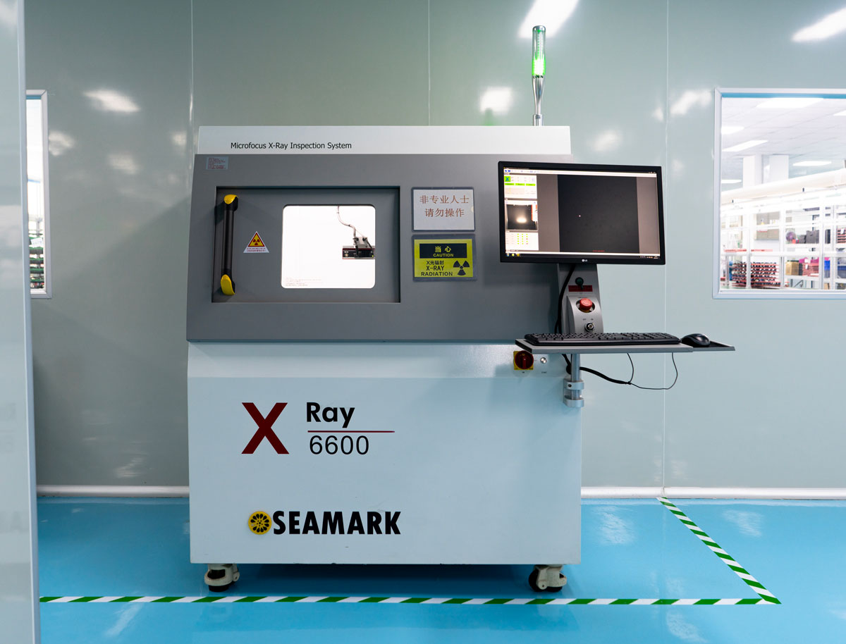
Inspection of a press-fit joint relies on force data, visual checks around the pin shoulder and continuity testing. X-ray is of limited use because the joint is mechanical rather than fused, but cross sectioning a sample from each lot shows whether the barrel has been deformed correctly and whether the plating is intact.
Rework is possible but limited. A pin can be pressed out and replaced once, and the hole must then be inspected for damage before a second insertion. Repeated extraction enlarges the barrel and destroys the interference that makes the joint work, so repair limits should be written down and enforced rather than left to operator judgement.
FAQ
What hole tolerance does a press-fit pin need? Most compliant pins specify a finished hole window of about seventy five to a hundred micrometres, and some fine pitch parts are tighter still. The number is always quoted as a plated diameter, so the fabricator must tune the drill size to hit that window after plating.
Can a loose press-fit joint be repaired? A single re-press is usually acceptable if the barrel is undamaged and the retention force still meets specification. If the hole is oversized or the plating is cracked, the connection should be replaced with a soldered or riveted alternative rather than pressed again.
Why measure insertion force instead of just checking continuity? Continuity proves that metal touches metal today, but it says nothing about contact pressure or long term stability. Insertion force confirms that the interference is correct, which is the only evidence that the joint will survive thermal cycling and vibration.