High-Mix Prototype PCB Assembly for Fast Development
A high-mix prototype build rarely fails for one dramatic reason. It fails because several small decisions drift apart at once. One board needs a fine-pitch part, the next needs a connector pressed through a plated hole, and a third carries both. Each change resets the stencil, the paste volume and the placement program. The run is short, so there is little time to settle the process before the next variant arrives. This guide sets out how to control that mix and keep the schedule intact.
Development teams use these builds to prove a design before tooling money is committed. The boards must be electrically sound and mechanically correct, yet the quantity stays small. That combination puts pressure on setup time, on component sourcing and on inspection. A supplier that treats a prototype like a scaled-down production order will lose days on changeovers. A supplier that plans the mix in advance can turn several variants around in one window. The difference sits in preparation, not in machine speed.
What High-Mix Assembly Means
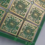
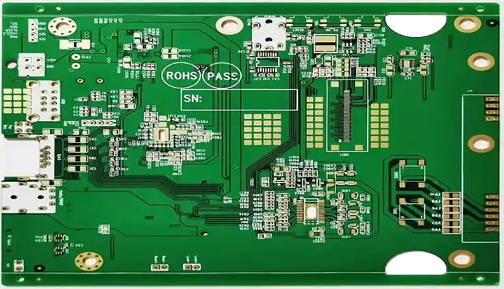
High-mix means several different board designs pass through the same line in a short period. Quantities per design are low, and the technical spread is wide. One design may use fine-pitch SMT parts and another may use large through-hole connectors. A third may combine both on one substrate. The line must switch between them without losing accuracy or traceability. This is the normal condition of prototype work, not an exception to it.
The main cost driver is not the number of boards but the number of switches. Every new design brings a fresh stencil, a new paste print, a new feeder setup and a new reflow profile. Engineers should expect the supplier to group similar designs where possible. Grouping cuts setup time and reduces the risk of a wrong program running on the wrong panel. Ask how the supplier plans the sequence before the order is placed.
Stackup Choices
The stackup sets the foundation for everything that follows. For prototypes, a simple two-layer or four-layer board often proves the circuit, but dense designs may need more layers. The choice affects drill sizes, impedance control and the reflow profile. A thicker board with heavy copper takes longer to heat, so the profile must change. Buyers should confirm the stackup against the actual signal and power needs, not against habit.
Surface finish also matters at this stage. A finish that suits fine-pitch SMT may behave differently on a board with large through-hole pads. The finish must survive multiple reflow passes if the board is assembled in stages. Engineers should state the finish on the fabrication drawing and check that the assembly house knows it. Small mismatches here surface later as poor wetting or weak joints, and they are hard to trace once the board is populated.
Lamination Control
Lamination quality decides whether the bare board survives assembly heat. Voids, resin starvation and misregistration can stay hidden until the first reflow cycle. A prototype lot is small, so one bad panel can spoil a whole build. The fabricator should control press cycles, cure schedules and layer alignment with records. Buyers rarely see these records, but they explain why one supplier yields clean boards and another does not.
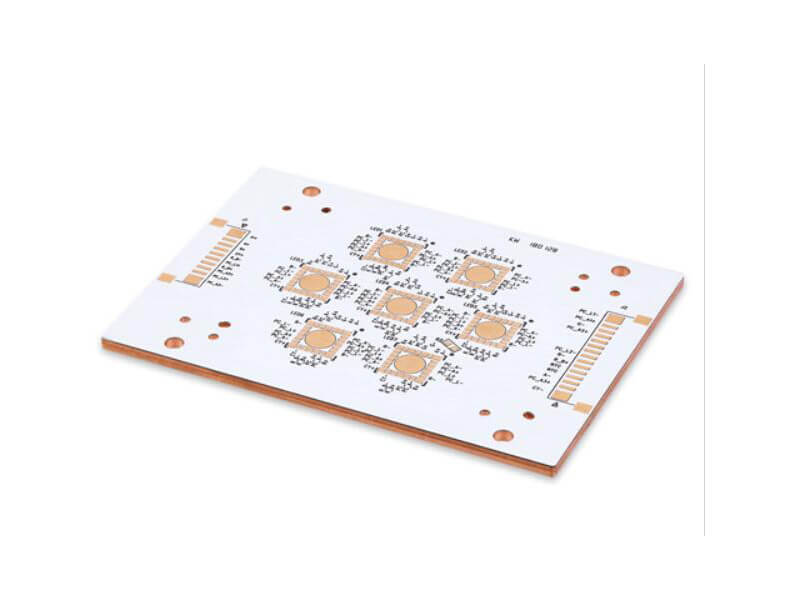
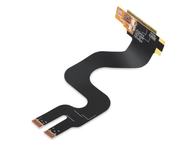
For mixed-material builds, the risk rises. Metal-base and flex substrates behave differently from rigid FR-4 under heat. They expand at different rates and need their own handling rules. If a prototype mixes these materials, the assembly plan must treat each one on its own terms. Ask the supplier to confirm the material, the press parameters and the inspection step for each substrate type before the build starts.
Drilling Risk
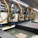
Drilling creates the vias and holes that carry both signal and mechanical load. Small drill sizes raise the risk of breakout, smear and plating defects. In a prototype, those defects may not appear until the board is tested under power. The fabricator should check drill registration, hole wall quality and plating thickness. A quick cross-section on the first panel gives useful evidence before the lot is released.
Through-hole components add a second concern. A hole that is slightly oversize makes hand soldering easy but weakens the joint. A hole that is undersize slows insertion and can crack the barrel. The drill chart and the component datasheet must agree. Engineers should verify this during the design review rather than at the assembly bench, where a fix costs time and possibly a new board lot.
Drill wear is another quiet factor in a short run. A bit that has cut too many holes produces a rough wall and a wider entry. On a prototype panel, the operator may not notice until plating fails or a pin fits loosely. Ask the fabricator how drill life is tracked and whether the first panel is checked before the rest of the lot. That single check often separates a clean build from a rework cycle.
Planning the Build Sequence
A high-mix run needs a sequence, not just a queue. The planner should group boards by thickness, finish and reflow profile so the oven settles once. Designs with similar paste requirements can share a print window. Boards with tall through-hole parts should come later, after the SMT stages are complete. This ordering cuts idle time and lowers the chance of a profile error on a short run.
Component sourcing belongs in the same plan. A missing part stops the whole sequence, not just one board. The bill of materials should be checked for availability, lifecycle status and package fit before the line is booked. Where a part is hard to find, an approved alternate keeps the schedule moving. Suppliers who review this early protect the delivery date. Buyers should treat the BOM review as a gate, not a formality.
Stencil management deserves its own place in the plan. Each variant needs its own apertures, and a reused stencil from a similar board can print the wrong paste volume. The supplier should label stencils by design revision and store them flat. When a revision changes a pad or a pitch, the old stencil must leave the line. Buyers can ask for the stencil revision in the build record, which makes a mix-up easy to spot later.
Assembly and Inspection
The assembly stage turns the bare board into a working unit. Paste printing, placement and reflow must be tuned for each design in the mix. Fine-pitch parts need accurate placement and controlled paste volume. Large through-hole parts need enough heat and a stable insertion. Mixed boards need both, and the order of operations matters. A clear process sheet for each variant prevents the wrong settings from carrying over.
Inspection closes the loop. Visual checks catch missing parts and polarity errors, while X-ray reveals hidden joints under area arrays. Electrical test confirms the board works as a circuit, not just as a set of joints. For fast development, the test plan should be defined early so fixtures and programs are ready. A structured PCBA testing plan turns inspection data into process feedback, which is what short runs need most.
First-article review is the point where the mix is proven. The team should compare the built board against the drawing, the BOM and the process sheet before the rest of the lot runs. Any deviation should be closed, not noted and carried forward. On a short run, one uncorrected error repeats across every panel. Buyers should ask who signs the first article and what evidence is kept, because that signature is the real release gate.
Choosing the Right Partner
Supplier selection should follow the mix, not the headline price. Ask how the factory handles changeovers, how it records settings and how it reports defects. A partner that runs SMT PCB assembly alongside through-hole work under one roof can keep the sequence short. A partner that outsources half the process adds handoffs, and each handoff adds delay and risk. The right questions are about control, not about slogans.
Engineering support matters just as much. A supplier that reviews Gerber data, the BOM and the pick-and-place file before booking the line will catch most problems early. That review should cover footprints, clearances, polarity marks and panel design. Buyers should also confirm how the supplier handles component procurement, since a turnkey model removes a large share of the coordination burden. A turnkey PCB assembly arrangement keeps fabrication, sourcing and assembly in one schedule.
For teams that need boards back quickly, speed must come from planning rather than from skipped checks. A fast quote is useful only if the build holds. Ask for the process sheet, the inspection records and the test report with the delivery. These documents show whether the run was controlled or merely finished. When the next design revision arrives, those records shorten the setup and reduce the risk of repeating a fault. That is the real value of a disciplined prototype partner.
Development schedules reward teams that plan the mix in advance. Group similar designs, confirm the stackup and finish, check the drill chart and clear the BOM before the line is booked. Keep one process sheet per variant and record the settings that ran. Then review the inspection and test data before the next build starts. Teams that want a fast first article can begin with rapid PCBA prototyping and scale the same controls into PCB assembly as volumes grow.