Rail Transportation PCB: Standards, Design Rules and Applications
What a Rail Transportation PCB Is
A rail transportation board is a printed circuit that lives inside the signalling, control, communication or power equipment of a train, a tram or a metro system. It is not simply an industrial board with a different label. It has to keep working through continuous duty, constant vibration, temperature swings from minus forty to plus eighty five degrees Celsius, humidity, dust and the electromagnetic environment created by traction drives and high power switching, and it has to do so for a service life measured in decades. The same requirements apply on the trackside as on the vehicle, and in both cases the consequences of a failure are operational rather than commercial.
The Standards That Define the Requirement
Four documents do most of the work. The railway vehicle electronics standard sets the supply voltages, the temperature classes and the requirements for design and testing of equipment installed on rolling stock. The fire safety standard for railway applications defines the smoke and flammability behaviour of the materials used, which pushes the choice of laminate and of conformal coating. The vibration and shock standard defines the mechanical environment and the test levels that the assembly has to survive. The railway electronic equipment specification covers the equipment level requirements, including supply and environmental behaviour. Underneath all of them, the printed circuit itself is normally built to the highest class of the rigid board qualification specification, which tightens the annular ring, the hole wall copper, the void limits and the inspection requirements. A project that quotes the class but does not trace it to the standards above it is only half specified.
Where These Boards Are Used
Signalling systems, from interlocking to track circuits and axle counters, are the safety critical group. Train control and management systems collect the vehicle state and distribute commands, and they sit at the centre of the network. Passenger information systems, displays, intercoms and camera installations are less critical but still expected to work continuously for years. Communication equipment carries the growing volume of data between the train and the trackside, and it is where high speed differential routing appears. Power and distribution equipment, including auxiliary converters and battery chargers, brings heavy copper and high voltage creepage into the picture. Security and access control systems, and the condition monitoring hardware used for predictive maintenance, complete the list; the last of these is growing quickly, because a sensor that reports a bearing problem before it becomes a failure is worth more than the cost of the fleet of boards it runs on.

Why Railway Boards Are Designed Differently
Continuous operation. Trains run for eighteen hours a day and more, and a board that fails takes a service with it. Design margins are therefore set higher than in consumer electronics, and redundancy is built into the architectures rather than bolted on afterwards.
Vibration and shock. Rail joints, switches and wheel flats produce repeated mechanical shocks. The failures they cause are usually the slow ones: a solder joint that cracks, a connector that frets, a heavy component that fatigues its own leads, or a screw terminal that loosens. Support of heavy parts, compliant lead forms and mechanically retained connectors do more for reliability here than any electrical change.
Temperature cycling. The board has to start in a cold depot and work under a hot roof, which drives the choice of a high glass transition laminate, careful thermomechanical design around through hole parts, and a coefficient of thermal expansion that matches the packages rather than the other way round.
Electromagnetic compatibility. Traction converters, pantograph arcing and high power switching create a hostile radio frequency environment. Return path design, plane integrity, filtering and shielding are functional requirements, not refinements.
Longevity and traceability. A vehicle stays in service for twenty to thirty years, so the design has to survive component obsolescence, and the manufacturer has to be able to produce data for a board built a decade earlier.
Design Rules That Follow From the Application
Work to the strictest class from the first layout review: the annular ring, the hole wall copper and the inspection rules for the highest class should be the defaults rather than something added after a review. Use thicker copper where current or thermal spreading demands it, and remember that heavy copper changes the achievable minimum line width and therefore the routing density. Apply conformal coating to protect against humidity and condensing conditions, and specify it in the drawing together with the areas that must be masked. Provide generous creepage and clearance for the traction and auxiliary supply voltages, and maintain it across the board rather than only at the connector. Design for the connector: press fit pins need a controlled hole tolerance and sufficient board thickness, and pluggable connectors need strain relief because vibration finds every unsupported mass. Consider thermal vias under power components and keep the heat path continuous into the chassis. Finally, design for test and for repair, because a board that cannot be diagnosed will be replaced as a unit, and the cost of that reaches the operator every time.
Materials and Their Trade-Offs
High glass transition FR-4 is the baseline for most rolling stock electronics, because it keeps its dimensional stability at the upper end of the temperature range and delaminates less during assembly. Where fire performance matters most, halogen free laminates are chosen to meet the smoke and toxicity requirements, and the choice of conformal coating follows the same standard. Communication equipment moving to high speed links needs low loss material with a controlled dielectric constant, which brings its own impedance discipline. Power conversion stages use heavy copper and sometimes metal backed boards, and both change the etching and plating process. The material decision is therefore driven by three questions: what temperature will the board see, what fire performance is required, and what data rate has to run through it.
Manufacturing Challenges Specific to Railway Work
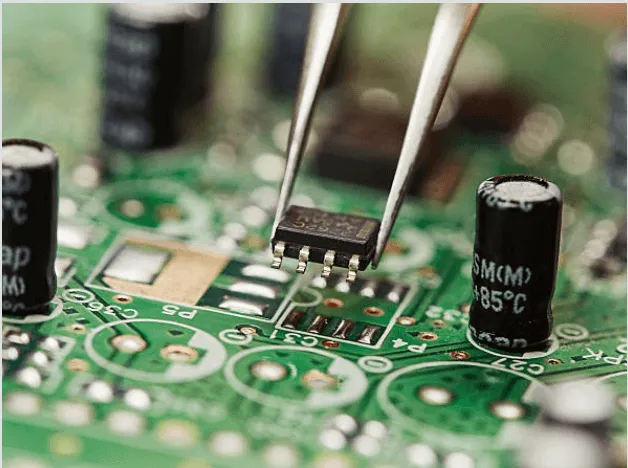
Thick copper is harder to etch uniformly, so line width tolerance has to be negotiated rather than assumed. Press fit holes require a tight finished diameter with plating that is consistent through the barrel, and that is a capability rather than a given. Back drilling is often needed on high speed links to keep the stub from degrading the channel. Conformal coating has to be applied with controlled thickness and full coverage of the intended area, which is a process to be qualified rather than a spray. Above all, the manufacturing record matters: the lot, the panel, the coupon data, the coating batch and the inspection results have to be retrievable years later, because the customer may be investigating a field failure long after the delivery.
What Drives the Cost
Cost follows the same factors as any high reliability board, with the multipliers set higher. Layer count and copper weight set the base, the material adds a premium over standard FR-4, and halogen free or low loss grades add more. Working to the highest class increases inspection and documentation effort. Conformal coating, press fit holes, back drilling and impedance control are each an extra operation. Small quantities of a certified build carry the qualification and test cost across few boards, which is why the first lot of a railway design is expensive and the volume price falls once the process is stable. Where the budget is tight, the place to look is the specification itself: review each requirement against the environment it will actually see, since carrying a test level that the installation never reaches is the most common source of unnecessary cost.
Where the Technology Is Going
Traction systems are moving to wide bandgap semiconductors, which switch faster and create sharper edges that stress the insulation of motors and the layout of gate drive boards. Train networks are consolidating onto Ethernet backbones, which brings controlled impedance differential routing into every subsystem. Condition monitoring is moving from periodic inspection to continuous sensing, adding more boards and more data. Functional safety requirements are spreading from signalling into subsystems that were previously treated as non safety related. None of these changes the fundamentals, but all of them raise the demands on layout discipline and on the documentation trail that has to accompany each delivery.
FAQ
What class of PCB is used in railway equipment? The highest class of the rigid board specification is the normal baseline for signalling and control hardware, and the equipment standards add their own environmental and test requirements on top.
Which standard covers railway electronics? The railway vehicle electronics standard covers supply and environmental requirements, the fire safety standard covers materials, and the vibration and shock standard covers the mechanical environment.
Why is conformal coating required? Humidity, condensation and contamination are continuous threats in a vehicle that operates through all seasons, and coating protects the surface insulation resistance over a service life of decades.
Can standard FR-4 be used? Often yes at the lower temperature classes, provided a high glass transition grade is chosen. Higher temperature classes and fire critical applications push towards more specialised laminates.
How long is a railway PCB expected to last? Fifteen to thirty years of service is a normal expectation, which is why component obsolescence planning and a retrievable manufacturing record matter as much as the electrical design.
Conclusion
A railway board is specified by its environment, not by its function alone: continuous duty, vibration, wide temperature range, aggressive EMC and a service life of decades. Design to the strictest class from the first revision, choose the laminate against the temperature and fire requirements, protect the assembly with controlled conformal coating, and keep the manufacturing record complete enough to answer a question ten years later. The dimensional and process limits to design against are listed in PCB capabilities, the high reliability layout conventions belong in PCB design and layout, and the coating and inspection steps are described in PCB manufacturing. Qualifying the design with a prototype PCB assembly build before the first certified lot is the cheapest way to find the thermal and mechanical problems in 2026.