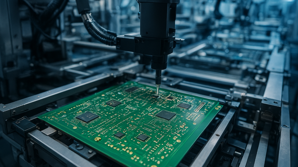
Reflow Preheat and Soak Zone Control for SMT Assembly
The first half of a reflow profile decides most of what happens in the second half. Preheat brings the assembly up to temperature without stressing it, and the soak zone gives flux time to activate and clean the surfaces before the solder melts. Get those stages wrong and no amount of peak temperature control will rescue the joints. This guide explains how gopcb sets preheat and soak parameters and how the result is verified.
What the Preheat Stage Is For
Preheat raises the whole assembly, board and components together, toward the point where solder will flow. Its purpose is to reduce the temperature difference between the oven and the product, so that the final ramp to reflow is short and controlled. A board that enters the peak zone cold will always lag its thermocouple.
Preheat also begins the work of the flux. As the temperature climbs, solvents evaporate and the flux softens and spreads over the surfaces to be joined. Starting that process gradually is what keeps the subsequent stages predictable, particularly on assemblies with heavy copper or large thermal mass. It also drives off moisture that the laminate absorbed in storage, which reduces the risk of delamination later in the cycle.

Ramp Rate and Thermal Shock
Ramp rate is the speed at which temperature rises, and it directly affects stress. A fast ramp heats the surface of a component before its interior, and the resulting differential expansion can crack ceramic bodies or lift a large BGA away from its pads. Slow ramps are gentler but increase cycle time and allow more oxidation. The practical target is the fastest ramp the components will tolerate, because a shorter time at elevated temperature means less oxidation overall.
Typical targets sit between one and three degrees per second up to the soak region, with tighter limits for ceramic parts and large modules. The correct figure comes from the component datasheets and from the assembly behaviour, not from a default in the oven software. Our thermal management notes explain how mass distribution affects the response.
The Soak Zone and Flux Activation
The soak zone holds the assembly at a temperature below melting for a defined period. During that time the flux fully activates, the volatile fractions leave the paste and the board reaches a uniform temperature across its area. Uniformity is the point: a board with hot and cold areas will not reflow evenly at the peak.
Soak length is a balance. Too short and the flux does not finish its work, which leaves poor wetting and more voiding. Too long and the flux is consumed before the solder melts, which produces the same result from the opposite direction. Flux activation requires both an adequate temperature and adequate time at that temperature.
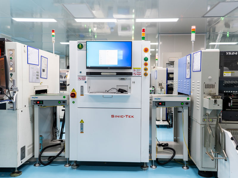
Balance Between Soak and Ramp Profiles
Two profile strategies dominate. The soak profile, sometimes called the ramp soak spike, holds a plateau to equalise temperature and activate flux. The straight ramp profile climbs continuously to peak, which shortens cycle time and reduces oxidation but demands more of the flux and of the components.
The choice depends on the assembly, and throughput matters as well, because a longer soak reduces the number of boards the oven produces in a shift. Boards with mixed mass, heavy connectors or many large thermal pads generally suit a soak profile because it equalises temperature before the peak. Simple, light boards with a good paste often run a ramp profile successfully and benefit from the shorter time at temperature.
Measuring the Profile Correctly
A thermal profile is only as good as the measurement behind it. Thermocouples must be attached to the actual joints of interest, not to the board surface or the oven rail. High temperature tape and adhesive are both used, and the joint must be covered so that the sensor reads the solder, not the air moving past it.
Several boards should be profiled, including one at the edge of the conveyor where heating is often different. The worst case is the assembly with the highest thermal mass, because it lags. Recording the measured profile rather than the oven settings is essential, since the oven display shows zone air temperature, not board temperature. The two can differ by tens of degrees, and the gap widens as the assembly becomes heavier.
Component and Board Mass Effects
Different assemblies absorb heat at very different rates. A thin board with small components follows the oven closely, while a thick board with a large metal connector may take twice as long to reach the same temperature. That difference is why a profile validated on one product cannot simply be copied to another.
Component mass matters within a single board too. A large shielded component can shadow the joints beside it, so the profile that suits the rest of the board may leave those joints cold. Positioning thermocouples at the slowest joints is the way to confirm the profile covers them.
Problems Caused by Poor Preheat
Insufficient preheat shows up as thermal shock damage, as solder spatter from rapid solvent release and as poor wetting where flux has not spread. Excess preheat dries the paste before reflow, which produces voids, solder balls and weak joints because the flux has already been consumed.
Uneven preheat produces defects that follow a pattern across the board. Joints near the conveyor edge may be cold while those in the centre are correct, and the difference appears as a consistent gradient rather than random variation. Recognising that pattern prevents wasted effort on the paste and stencil, as our notes on solder defects describe.
Setting Zones on the Oven
Oven zone temperatures and conveyor speed together produce the profile. Raising a zone temperature and slowing the conveyor both increase the heat delivered, but they change the shape of the curve differently. Adjusting one at a time and re-profiling keeps the effect of each change clear.
The oven itself drifts over time. Heating elements age, thermocouples fail and blower performance changes, so the profile should be re-verified on a schedule and after any maintenance. Zone calibration records belong with the equipment history rather than in a separate file. Where one oven runs several products, storing the profiles together makes a drift in one of them much easier to spot.
Verification and Documentation
Verification means profiling the product again after any change to the oven, the paste, the board or the component mix. The measured profile should be stored with the product record, including the thermocouple positions so that a later check reproduces the same measurement.
Production control then relies on confirming that the oven is delivering that profile. Daily checks of conveyor speed, zone temperatures and profile on a reference board catch drift early. The assembled result should also be confirmed at the end of the line with optical inspection, which turns a good profile into evidence of good joints.
FAQ
What is the difference between preheat and the soak zone? Preheat is the initial rise from ambient to the soak region, and the soak zone is the plateau that follows. Preheat controls the rate of heating to avoid thermal shock, while the soak equalises temperature and gives flux time to activate.
How long should a soak zone last? Long enough for the whole assembly to reach a uniform temperature and for the flux to activate, which is typically sixty to ninety seconds for common lead free pastes. The correct value should be established by profiling the actual product.
Can I use one profile for several products? Sometimes, if the boards are similar in mass and layer count. Where mass differs significantly the profile must be validated separately, because a profile that works on a thin board can leave a heavy assembly well below the required temperature.