
RF Connector Plating, Sealing And Corrosion
An RF connector is a mechanical interface that must also be an electrical one, and the two requirements conflict. Good contact needs pressure and hardness; good weather resistance needs a sealed joint; low loss needs a smooth plated surface. Where a product is used outdoors, the compromise is usually made badly, and the result is a link whose performance degrades over a few seasons.
This article covers the plating systems used on RF connectors, why some of them fail outdoors, and the sealing and board-level measures that extend service life.
The reason the subject deserves attention is that connector degradation is not a sudden failure. The insertion loss rises gradually, the return loss worsens, and the system continues to work until the margin is gone.
Plating Systems And What They Do
Three plating systems dominate. Gold over nickel gives the most stable contact resistance and resists oxidation, at a cost that limits its use to the contact surfaces. Silver over copper or brass gives the lowest resistance at a lower cost, but silver tarnishes readily, and the tarnish layer is a poor conductor. Nickel alone is hard and wear resistant but forms an oxide that raises contact resistance.
The choice depends on the number of mating cycles and the environment. Gold is preferred where the connection is made and broken repeatedly, because it does not form a resistive film. Silver is common where the connection is permanent and the resistance must be minimal. The thinner the plating, the faster it wears through to the layer below, and the point at which that happens is the end of the connector’s useful life.
Why Outdoor Installations Fail
Moisture is the vehicle for most of the failure mechanisms. Water that enters the connector body can reach the junction between the plating and the base metal, and where two dissimilar metals and an electrolyte are present, galvanic corrosion begins. The corrosion products increase the contact resistance and, in the worst case, consume the plating entirely.
Temperature cycling adds a mechanical component. The connector body, the cable and the board expand at different rates, and the movement works the contact surfaces against each other. Small movements at the contact point cause fretting, which removes plating and produces oxide debris that is a poor conductor. The combination of moisture and movement is what makes an outdoor connector fail rather than either effect alone.
Sealing And Water Pathways
Water rarely enters through the plated joint. It enters along the cable, through the interface between the connector and the panel, or through a poorly sealed cable entry. Once inside the body, capillary action carries it to the contact surfaces. Sealing the outer interface without sealing the cable entry leaves the internal path open.
The countermeasures are a gasket at the panel interface, a heat shrink or moulded boot at the cable entry, and a means of draining the assembly if water can accumulate. A connector mounted on the underside of a housing with the interface pointing upward collects water; the same connector mounted downward sheds it. Orientation is often the simplest fix available, and it is a mechanical decision rather than an electrical one.
The Board Side Of The Connector
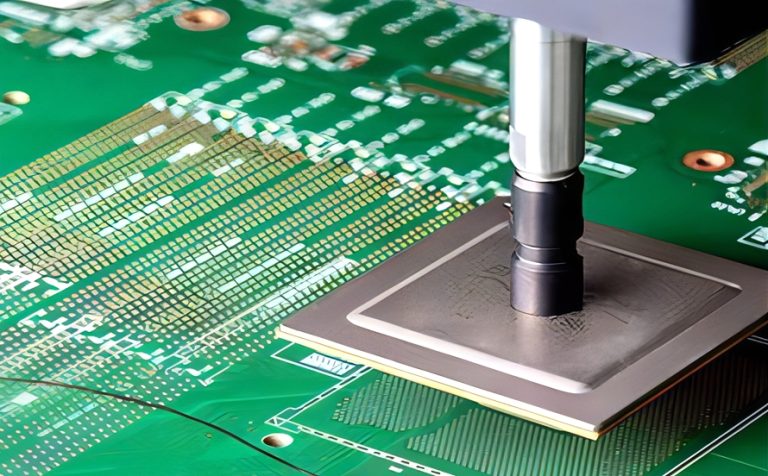
Corrosion also occurs on the board. A connector soldered with a finish that tarnishes, or one whose shield is grounded through a poor connection, creates a path where moisture and current coexist. Where the assembly will be exposed, the board finish and the coating on the board both contribute to the life of the connection.
Immersion finishes and their limitations are covered in the guidance on the tin to copper interface, and the same principles apply at a connector. Where the board is coated, the coating must not wick into the connector, and the protective function of the coating depends on the connector area being masked and sealed rather than covered.
The cable is part of the same system and often the weakest part. A cable whose jacket is damaged, whose shield is poorly terminated or whose connector was assembled in the field will admit moisture regardless of the quality of the board mounted connector. Where a link fails, the cable assembly should be examined before the connector is replaced.
Contact Resistance And Its Measurement
The electrical signature of a degrading connector is a rising contact resistance and a worsening return loss. Low frequency resistance is easy to measure and is a useful indicator, but the RF behaviour is what matters for the link, and it is measured as insertion loss and return loss through the connector.
Measuring a connector’s contribution separately requires a reference, usually a pair of connectors joined by a known length of cable or a calibrated through. The comparison should be repeated after a humidity and temperature exposure, because a connector that measures well when new may not after a few cycles. The contact and finish behaviour during test is a useful reminder that probe contacts have the same physics as connector contacts.
Wear And Mating Cycles
The number of mating cycles is quoted for a connector under specified conditions, and it is reduced by contamination and by damage to the mating surfaces. A connector that is mated with the wrong torque, or whose threads are cross started, damages the surfaces on the first use and then degrades quickly.
Where a connector will be mated repeatedly in service, the design should provide a sacrificial interface: a short cable assembly that can be replaced, or a bulkhead connector that takes the wear and can be exchanged without disturbing the board. The cost is small compared with the cost of replacing a board because a connector wore out.
Design For The Environment
The design decisions that extend life are mostly mechanical. Keep connectors away from the lowest point of an enclosure, protect the cable entry, provide a gasket surface that is flat and clean, and choose plating according to the environment rather than only by the electrical specification.
Where the environment is severe, the assembly should be qualified in that environment rather than by a calculation. A humidity and temperature cycling test with the connector assembled as it will be installed will find the pathways that a specification review does not, and the result is a design that survives the installation rather than one that passes a data sheet.
Shielding continuity matters electrically as well as environmentally. A connector whose shell is grounded through a long thin trace or a single via provides a poor return for the shield current, and the resulting common mode current appears as emissions and as a change in the link behaviour when the cable is moved. Bonding the shell to the chassis or to a solid ground area with multiple short connections is what makes the shield effective.
FAQ
Is gold always the best plating? It is the most stable for repeated mating, but it is soft and thin gold wears through quickly. Where the connection is permanent, a silver or even a nickel finish can be adequate and considerably cheaper.
Can grease be used to protect a connector? A dielectric grease excludes moisture and is widely used outdoors, provided it is compatible with the connector’s materials and does not contaminate the contact surfaces. It should not be used where it can migrate into a signal path.
How is a corroded connector detected early? By periodic measurement of insertion loss and return loss against a baseline, and by visual inspection for discolouration at the interface. Waiting for the link to fail removes the warning the measurement would have provided.