RF PCB Substrate Material: The Complete Guide to High-Frequency Laminate Selection for 5G and mmWave Designs
Selecting the right RF PCB substrate material is the single most consequential decision in high-frequency circuit design—it directly determines signal integrity, insertion loss, impedance accuracy, and overall system performance. For applications above 1 GHz, standard FR-4 becomes impractical due to its high dissipation factor (Df ≈ 0.020) and unstable dielectric constant. This guide provides a comprehensive comparison of PTFE, Rogers hydrocarbon ceramic, and emerging ultra-low-loss laminates, with actionable selection criteria for 5G infrastructure, automotive radar, and satellite communications.
Why RF PCB Substrate Material Selection Matters
At frequencies above 1 GHz—and especially in the 24–77 GHz mmWave bands driving 5G and automotive radar—the laminate’s dielectric properties directly determine signal loss, impedance accuracy, and overall system performance. The substrate is not merely a physical carrier for components; it is a fundamental dielectric component that governs signal velocity, phase stability, and insertion loss. As operating frequencies move from MHz into GHz and beyond 40 GHz, standard PCB substrates like FR-4 increasingly fall short.
The RF PCB substrate material you choose impacts every aspect of your design: electrical performance (signal integrity, loss, impedance control), thermal management (heat dissipation, CTE matching), manufacturability (drillability, lamination, plating), and total cost of ownership. For engineers designing 5G base stations, phased array antennas, or 77 GHz automotive radar sensors, understanding the trade-offs between material families is essential for achieving first-pass success.
At gopcba, we specialize in manufacturing high-frequency PCBs using a wide range of RF substrate materials, from standard Rogers RO4000 series to ultra-low-loss PTFE laminates. Our engineering team has extensive experience in material selection, impedance control, and DFM optimization for 5G, automotive, and aerospace applications.
Key Performance Parameters of RF PCB Substrate Materials
Dielectric Constant (Dk, εr)
Dk determines trace geometry for a target impedance. For RF designs, you need low Dk (2.2–3.5) for wider traces and reduced fabrication sensitivity, stable Dk across the frequency range (±0.02 or better), stable Dk across temperature (-40°C to +85°C typical operating range), and low moisture absorption (water has Dk ≈ 80; absorbed moisture shifts Dk dramatically). A lower Dk means faster signal propagation through the transmission line, while a higher Dk increases parasitic capacitance but allows smaller trace dimensions (beneficial for miniaturized designs).
Dissipation Factor (Df, Tan δ)
Df represents the proportion of electromagnetic energy absorbed (converted to heat) as it passes through the dielectric. Df directly translates to insertion loss. At 28 GHz, the difference between Df = 0.0009 (Rogers RT/duroid 5880) and Df = 0.004 (Rogers 4350B) means approximately 0.5 dB/cm additional loss—critical in antenna feed networks and long transmission lines. In RF/microwave circuits, an extremely low Df is essential to minimize signal attenuation.
Thermal and Mechanical Properties
CTE (Coefficient of Thermal Expansion): Z-axis CTE causes via stress during reflow. Tg (Glass Transition Temperature): Must exceed all processing and operating temperatures. Thermal conductivity: Important for power amplifier boards. Moisture absorption: Critical for maintaining stable electrical properties in humid environments—most Rogers materials absorb less than 0.02% moisture.
Major RF PCB Substrate Material Families
PTFE (Polytetrafluoroethylene / Teflon) — The Gold Standard
PTFE offers the best dielectric performance among all organic resin materials. PTFE is a non-polar polymer that exhibits almost zero molecular polarization even at extremely high frequencies, resulting in an electrically “transparent” substrate that allows signals to travel further with less distortion. Dk characteristics: Extremely low and stable, typically 2.14–2.55, with minimal variation across the 1–10 GHz wideband range. Df characteristics: Extremely low, approximately 0.0002–0.0004 at 10 GHz—two orders of magnitude lower than FR-4.
However, pure PTFE presents significant manufacturing challenges. It is soft, prone to “cold flow” (deformation under pressure), and has a massive coefficient of thermal expansion (CTE). To make it a viable PCB substrate, manufacturers reinforce the PTFE matrix with woven glass or ceramic fillers. The gold standard for lowest-loss RF substrates is Rogers RT/duroid 5880, with Dk = 2.20 ± 0.02 and Df = 0.0009 at 10 GHz.
Rogers RO4000 Series — The Industry Workhorse
The RO4000 series has become the default choice for most commercial RF applications. These hydrocarbon ceramic laminates offer PTFE-like electrical performance with epoxy/glass processability. RO4000 materials use ceramic-filled hydrocarbon resin with woven glass reinforcement, providing excellent high-frequency performance and low-cost circuit fabrication.
The most popular variant, RO4350B, offers a Dk of 3.48 (±0.05) and Df of 0.0037 at 10 GHz while remaining compatible with standard PCB processing equipment. RO4000 series materials balance RF performance with standard FR-4 processability, and fabricators love them because they process exactly like FR-4. The RO4003C variant offers even lower loss with Df = 0.0027 at 10 GHz, approximately 27% lower than RO4350B.
For designs operating above 20 GHz, RO4350B’s higher loss becomes a limiting factor, making pure PTFE or RO3000 series materials more appropriate.
Rogers RO3000 Series — Ceramic-Filled PTFE
RO3000 series high-frequency circuit materials are ceramic-filled PTFE composites intended for use in commercial microwave and RF applications. These materials combine the ultra-low loss of PTFE with improved dimensional stability from ceramic fillers. Key variants include RO3003 (Dk ≈ 3.0, low loss), RO3006 (Dk ≈ 6.15, higher Dk for size reduction), and RO3010 (Dk ≈ 10.2 for extreme miniaturization). The RO3035 variant provides design solutions for 5G, millimeter wave sub-6GHz, and massive MIMO applications.
Emerging Ultra-Low-Loss Materials
Material manufacturers are releasing next-generation ultra-low-loss laminates with Df below 0.002 at 10 GHz, reshaping the competitive landscape for 5G base station and phased array antenna PCB fabrication. Key announcements include Rogers RO4730G3 (ceramic-filled PTFE with Dk 3.0, Df 0.0025 at 77 GHz—targeting next-gen automotive radar where every 0.001 Df improvement extends detection range), Panasonic Megtron 7 (Dk ≈ 3.3, Df ≈ 0.002 at 10 GHz with full FR-4 processing compatibility), and Isola Astra MT77 (Dk ≈ 3.0, Df ≈ 0.0017 at 10 GHz, combining PTFE-like electrical performance with modified epoxy processability).
RF PCB Substrate Material Comparison Table
| Material | Dk @ 10 GHz | Df @ 10 GHz | Tg (°C) | CTE-Z (ppm/°C) | Moisture Absorption (%) | Relative Cost (vs FR-4) | Best For |
|---|---|---|---|---|---|---|---|
| FR-4 (Standard) | 4.1–4.8 | 0.015–0.025 | 130–170 | 50–70 | 0.10–0.15 | 1× | <1 GHz, digital circuits |
| Rogers RT/duroid 5880 (PTFE/Glass) | 2.20 ±0.02 | 0.0009 | N/A (熔点327°C) | 24 | <0.02 | 5–10× | mmWave, aerospace, space-grade |
| Rogers RO4350B (Hydrocarbon Ceramic) | 3.48 ±0.05 | 0.0037 | >280 | 32 | 0.06 | 3–5× | 5G sub-6 GHz, WiFi, GPS to ~20 GHz |
| Rogers RO4003C (Hydrocarbon Ceramic) | 3.38 ±0.05 | 0.0027 | >280 | 46 | 0.06 | 3–5× | Moderate mmWave, low-loss RF |
| Rogers RO3003 (Ceramic-filled PTFE) | 3.00 ±0.04 | 0.0010 | N/A | 17 | <0.02 | 5–8× | mmWave, 5G, automotive radar |
| Panasonic Megtron 7 (R-5785N) | 3.3 | 0.002 | >200 | — | — | 3–6× | Sub-6 GHz antenna feed, 112G SerDes |
| Isola Astra MT77 | 3.0 | 0.0017 | >200 | — | — | 4–7× | 5G massive MIMO, PTFE-like performance |
Data compiled from manufacturer datasheets and industry publications.
FR-4 vs. RF Substrates: When to Make the Switch
FR-4 (epoxy resin + glass fiber) is the most affordable and widely processed substrate material available today. However, its Dk is unstable at high frequencies and drops significantly as frequency increases, and its relatively high loss (Df ≈ 0.015–0.020) makes it only appropriate for low-frequency analog or general digital circuits. Above 1 GHz, FR-4’s high dielectric loss and unstable Dk cause severe signal attenuation and distortion. Standard FR-4 becomes impractical above ~3 GHz.
The switch to RF-grade substrates is mandatory when operating above 2–3 GHz, when insertion loss becomes unacceptable, or when Dk stability is critical. For 5G mmWave and radar applications in the 24–77 GHz range, full Rogers or PTFE materials are required—FR-4 is unusable above 10 GHz.
Cost Considerations for RF PCB Substrate Materials
Substrate material is the single biggest cost driver in RF PCB manufacturing—Rogers and PTFE laminates cost 3–10× more than FR-4 per square inch. RO4000 series (hydrocarbon/ceramic, easy to process) typically adds 2–5× cost compared to equivalent FR-4 boards, while PTFE-based materials (RO3000, RT/duroid) add 5–10× cost and require plasma treatment and specialized handling. Pure PTFE substrates deliver the lowest loss available in a commercial laminate, but they cost 5–10× more than FR-4 and require specialized fabrication, with 1–2 weeks of additional lead time.
For high-volume production, RO4000 series materials offer a compelling cost-performance advantage because they can be processed on standard FR-4 manufacturing lines, reducing fabrication costs by approximately 30% compared to pure PTFE. The cost premium for RO4000 is 3–5× FR-4 but far less than pure PTFE.
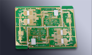
When cost is a primary constraint and frequencies are below 10 GHz, RO4350B provides an excellent balance of performance and manufacturability. For extreme performance requirements above 20 GHz, the additional cost of PTFE or RO3000 series materials is justified by the significant reduction in insertion loss.
Manufacturing Considerations for RF PCB Substrates
PTFE Processing Challenges
PTFE materials require specialized fabrication processes. The non-polar nature of PTFE makes copper adhesion difficult—surface treatments such as plasma etching or sodium naphthalene etching are required before plating. Drilling requires optimized parameters and specialized drill bits to prevent smearing and burr formation. Lamination requires higher temperatures and pressures than standard FR-4. These challenges add cost and lead time but are manageable for experienced RF PCB manufacturers.
RO4000 Series Processing Advantages
RO4000 series materials process exactly like FR-4—they can be drilled, etched, and plated using standard equipment without special PTFE handling. This compatibility with standard FR-4 processing greatly lowers the manufacturing门槛 and enables high-volume production. The materials are compatible with lead-free assembly and widely available with moderate cost.
Copper Foil Selection
For mmWave applications, VLP (Very Low Profile) or HVLP (High Volume Low Profile) copper foils with surface roughness Rz ≈ 1.5 μm are mandatory. Smoother copper reduces conductor loss at high frequencies, which becomes a significant contributor to total insertion loss above 10 GHz.
Application-Specific RF PCB Substrate Selection Guide
5G Sub-6 GHz Infrastructure (3.3–4.9 GHz)
Massive MIMO systems operating in n77/n78 bands use antenna arrays with 32 to 64 elements per panel. At these frequencies, dielectric loss is meaningful but not dominant. Primary material challenges are Dk stability across temperature (for beam steering accuracy), CTE matching to components, and processability in high-layer-count builds. Recommended materials: Rogers RO4350B (cost-effective, processable), Panasonic Megtron 7 (ultra-low loss, good processability), or Isola Astra MT77 (PTFE-like performance with standard processing).
5G mmWave (24–48 GHz, n257/n258/n260/n261)
At 28 GHz, even materials classified as “low-loss” (Df ≈ 0.004 at 10 GHz) introduce 0.8–1.0 dB/inch of dielectric loss on stripline layers. For phased array antenna PCBs where feed network traces may run 3–5 inches, this loss directly reduces effective isotropic radiated power (EIRP) and receiver sensitivity. Recommended materials: Rogers RT/duroid 5880 (Df = 0.0009, lowest loss), Rogers RO3003 (ceramic-filled PTFE, Df = 0.0010), or Rogers RO4730G3 (optimized for 77 GHz automotive radar).
Automotive Radar (77 GHz)
77 GHz automotive radar sensors demand the lowest possible loss and highest Dk stability. Rogers RO4730G3 offers Dk 3.0 and Df 0.0025 at 77 GHz, specifically targeting next-gen automotive radar where every 0.001 Df improvement extends detection range. RO4000 series laminates have been well established as reliable circuit materials for 24 GHz vehicular radar sensors.
Aerospace and Satellite Communications
Space-grade applications require materials with the lowest loss, excellent thermal stability, and low outgassing. Rogers RT/duroid 5880 is the gold standard for space-grade antennas and phased array systems. PTFE materials deliver the best electrical performance for demanding RF applications.
Emerging Trends in RF PCB Substrate Materials
The RF PCB substrate material landscape is evolving rapidly. IMS 2026 Boston showcased several trends directly affecting RF PCB fabrication: sub-100 µm line/space processes enabling tighter mmWave antenna arrays, new ultra-low-loss laminates targeting 6G research bands above 100 GHz, advanced packaging convergence where PCB substrate requirements merge with IC substrate specs for 5G front-end modules, and increased emphasis on thermal management solutions integrated into RF board stackups for GaN amplifier mounting.
Material manufacturers are pushing dissipation factors below 0.002 at 10 GHz. Panasonic’s upcoming Megtron 8 targets Df below 0.0015 at 10 GHz with improved Dk uniformity (±2% across the panel), potentially challenging PTFE-based systems in mmWave applications while maintaining thermoset resin processing compatibility. AGC (Asahi Glass) is developing fluoropolymer-based laminates for 100+ GHz 6G research applications.
Sustainable materials are also emerging. Recent research introduced a recyclable hemp-derived poly(cannabidiol-carbonate) (PCBDC) substrate as a sustainable low-loss material for 5G, microwave, and millimeter-wave electronics.
RF PCB Substrate Material Selection Decision Framework
- Step 1: Define operating frequency range. Below 1 GHz → FR-4 may suffice. 1–10 GHz → RO4350B or equivalent. 10–20 GHz → RO4003C or low-loss hydrocarbon. Above 20 GHz → PTFE, RO3000 series, or ultra-low-loss materials.
- Step 2: Determine loss budget. Calculate acceptable insertion loss for your signal chain. Each 0.001 reduction in Df translates to approximately 0.5 dB/cm less loss at 28 GHz.
- Step 3: Evaluate thermal requirements. Ensure Tg exceeds all processing and operating temperatures. For power amplifiers, consider thermal conductivity.
- Step 4: Assess manufacturability. RO4000 series processes like FR-4, reducing cost and lead time. PTFE requires specialized handling.
- Step 5: Consider moisture sensitivity. For outdoor or high-humidity applications, low moisture absorption materials (<0.02%) are critical.
- Step 6: Factor in cost. RO4000 series = 3–5× FR-4. PTFE = 5–10× FR-4. Choose the lowest-cost material that meets all performance requirements.
Frequently Asked Questions About RF PCB Substrate Materials
What is the best RF PCB substrate material for 5G applications?
For 5G sub-6 GHz, Rogers RO4350B offers the best balance of performance, processability, and cost. For 5G mmWave (24–48 GHz), Rogers RT/duroid 5880 or RO3003 provide the lowest loss.
Why is PTFE preferred for high-frequency PCBs?
PTFE is a non-polar polymer with extremely low dissipation factor (Df ≈ 0.0009) and stable dielectric constant across frequency and temperature, making it ideal for frequencies above 10 GHz.
Can Rogers RO4350B be processed like FR-4?
Yes. RO4350B uses a thermoset hydrocarbon ceramic-filled resin system that processes exactly like FR-4 with standard drill, etch, and plating equipment. This is a key advantage over PTFE materials.
What is the difference between Rogers RO4000 and RO3000 series?
RO4000 series are hydrocarbon ceramic laminates that process like FR-4 with Df ≈ 0.0027–0.0037. RO3000 series are ceramic-filled PTFE composites with lower loss (Df ≈ 0.0010–0.0015) but require specialized PTFE processing.
How does moisture affect RF PCB substrate performance?
Water has a dielectric constant of approximately 80. Absorbed moisture shifts Dk dramatically, degrading impedance control and signal integrity. RF-grade materials typically have moisture absorption below 0.02%.
What is the cost difference between FR-4 and Rogers materials?
RO4000 series typically costs 3–5× more than FR-4. PTFE-based materials cost 5–10× more. The cost premium is justified by the significant performance improvements at high frequencies.
What new RF PCB substrate materials were announced at IMS 2026?
IMS 2026 featured Rogers RO4730G3 (optimized for 77 GHz automotive radar), Panasonic Megtron 7 samples with Df 0.002 at 10 GHz, AGC fluoropolymer laminates for 100+ GHz 6G research, and Isola’s updated Astra MT77 with improved Dk consistency.
Key Takeaways for RF PCB Substrate Material Selection
- RF PCB substrate material selection is the most critical decision in high-frequency design—it directly determines signal integrity, loss, and system performance.
- FR-4 becomes impractical above approximately 3 GHz due to high loss (Df ≈ 0.020) and unstable Dk.
- PTFE materials offer the lowest loss (Df ≈ 0.0009) but require specialized fabrication and cost 5–10× more than FR-4.
- Rogers RO4000 series provides PTFE-like electrical performance with FR-4 processability at 3–5× the cost of FR-4—the industry workhorse for commercial RF applications.
- RO4350B (Dk 3.48, Df 0.0037) is the most popular choice for 5G sub-6 GHz designs.
- RO4003C offers 27% lower loss than RO4350B (Df 0.0027) for moderate mmWave applications.
- Emerging ultra-low-loss materials (Df < 0.002 at 10 GHz) from Panasonic, Isola, and Rogers are expanding options for 5G infrastructure and mmWave designs.
- For mmWave applications above 20 GHz, PTFE or RO3000 series materials are required.
- Select the lowest-cost material that meets all electrical, thermal, and manufacturability requirements for your specific application.
Get Expert RF PCB Manufacturing Support
Choosing the right RF PCB substrate material is just the first step. Successful high-frequency PCB fabrication requires precise impedance control, tight Dk/Df characterization, and manufacturing expertise with specialized materials. At gopcba, we provide end-to-end RF PCB manufacturing services including material selection consulting, DFM analysis, impedance-controlled fabrication, and assembly.
Our capabilities cover the full spectrum of RF PCB substrate materials—from Rogers RO4000 series and PTFE laminates to emerging ultra-low-loss materials for 5G and mmWave applications. We offer prototype PCB assembly, low-volume PCB assembly, and high-volume PCB assembly with rigorous quality control and fast turnaround.
Get a free material selection consultation and DFM analysis for your RF PCB project. Contact our engineering team today to discuss your specific substrate requirements and receive expert guidance on the optimal material choice for your application.
References
- AtlasPCB. (2026). Rogers vs PTFE Laminates for RF PCB Design: Material Selection Guide for 5G and mmWave Applications.
- PCBSync. (2025). Rogers PCB Materials: Complete Guide to RO4000, RO3000, RT/duroid & All Series Laminates Compared.
- AtlasPCB. (2026). IMS 2026 Boston: Key RF PCB Technology Developments.
- Rogers Corporation. RO4000® Series and RO3000® Series Datasheets.
- AtlasPCB. (2026). High-Frequency Microwave PCB Substrate Selection.
- PCBSync. (2026). PTFE PCB Laminates Explained: High Frequency Material Selection Guide.
- AtlasPCB. (2026). New Ultra-Low-Loss PCB Laminates Target Sub-6 GHz.
- PCBSync. (2026). Arlon DiClad 880: Ultra-Low Dk PTFE PCB Laminate for High-Speed RF Design.