Rigid-Flex Design: Bend Radius and Layers
What Makes Rigid-Flex Different
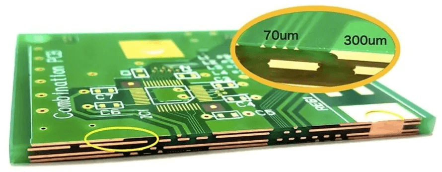
A rigid-flex board is a single construction that contains both rigid sections with multiple copper layers and a flexible section that bends. The layers are continuous across the boundary, so the flexible area is made of the same stack as the rigid, minus the material that would make it stiff. The design therefore has to be done as one board rather than as two boards joined by a cable, and the constraints of the flexible area apply to the routing and the layer assignment of the rigid areas as well. This is the source of most of the difficulty in a rigid-flex project.
Bend Radius and Flex Life
The bend radius is the most important number in a flexible design. The strain in the outer copper layer is proportional to the distance from the neutral axis divided by the bend radius, so a thin stack or a large radius keeps the copper inside its elastic limit. The rules of thumb vary with the construction, but a dynamic application typically needs a radius many times the total thickness of the flexible stack, while a bend that is formed once during assembly can use a much tighter radius. The layers that carry the traces should be kept near the neutral axis, which in practice means designing the stack so that the copper layers of the flexible area are symmetric about the middle.
Layer Planning Across the Transition
Every copper layer in the flexible area must be present in the rigid areas, but not every copper layer in the rigid areas can extend into the flexible area, because a plane or a thick copper layer would make the flex stiff and brittle. The standard approach is to define which layers continue through the bend, usually the outer layers or a dedicated flex core, and to remove the others by designing the stack so that they simply do not exist in that region. The routing that crosses the boundary therefore has to be on the continuing layers, and the layer change before the transition has to be planned, because a via inside the bend area is a stress concentrator.
What Must Not Be in the Bend Zone
The bend area should contain only copper traces and the flexible dielectric with its coverlay. Vias, plated through-holes, large copper pours, silkscreen and any component must stay outside it. Traces should cross the bend perpendicular to the bend line rather than at an angle, and they should be distributed evenly rather than bunched at one edge, because an uneven distribution concentrates the strain. Where a plane is needed in the flex for impedance control, it should be a cross-hatched or a narrow strip pattern rather than a solid sheet, since a solid sheet substantially increases the stiffness and the risk of cracking. The transition from the bend area to the rigid area should itself be outside the bend, since the stiffening material creates a step where the strain concentrates.
Coverlay, Adhesive and Thickness
The flexible area is protected by a coverlay, which is a polyimide film with an adhesive, rather than by solder mask, because mask is not flexible enough and cracks during bending. The coverlay opening follows the same logic as a mask opening: it exposes the pads that must be soldered or probed and covers everything else. The adhesive that bonds the coverlay and the layers adds thickness and can flow during lamination, so the openings have to be designed with a tolerance that accounts for the flow. The total thickness of the flexible stack, including the coverlay adhesive, is what appears in the bend radius calculation, so the choice of coverlay thickness affects the mechanical design rather than only the surface finish.
The Rigid Areas and Their Finish
The rigid sections are built like any multilayer board, but they have to survive the flexible section being formed and folded. The usual issues are the finish and the surface protection: a flexible circuit is often assembled before folding, so the finish must tolerate the folding operation without cracking, and the plating in the rigid areas should not be brittle. The stiffener, usually a sheet of polyimide or FR4 bonded to the flex where a connector is mounted, has to be positioned so that it does not extend into the bend. Where the assembly will be folded after reflow, the fold should be planned and even tooled, because a fold done by hand is not repeatable and can crack the copper.
Design Checks
Check the bend radius against the total flex thickness and the intended number of cycles. Confirm that no via, plane or component lies in the bend zone. Check that every layer that crosses the boundary is defined in both the rigid and the flexible areas. Confirm the coverlay openings against the pads and the adhesive flow. Verify the stiffener positions and the fold direction. Finally, confirm the whole thing with a bend test on a sample before committing to production, because the interaction between the adhesive, the copper and the bend radius is difficult to predict from a drawing.

FAQ
What bend radius should I use? It depends on the flex thickness and the number of cycles. A one-time fold can be tight; a dynamic application needs a radius many times the stack thickness.
Can I place a via in the bend area? No. A via is a stress concentrator and should be kept outside the bend zone along with planes and components.
Why not use solder mask on the flex? Because it is not flexible enough and cracks during bending, which is why a polyimide coverlay is used instead.
Should the flex contain a ground plane? Only if it is required for impedance, and then as a cross-hatched or narrow pattern rather than a solid sheet.
When is a rigid-flex worth it? When the product needs a controlled impedance connection across a moving joint, when connector count has to be reduced, or when space and reliability both matter.
Conclusion
Rigid-flex design is decided by the bend, so the bend radius, the flex thickness and the layers that cross the transition come first and the rigid layout follows. Keep vias, planes and components out of the bend zone, use a coverlay rather than mask, and verify the assembly with a bend test. Flexible construction capability is described under PCB capabilities, the layup and lamination steps belong to PCB manufacturing, and the bend and routing rules are part of PCB design and layout. Rigid-flex assemblies are normally proven through flex PCB assembly in 2026.