
Rigid-Flex PCB Manufacturing: A Buyer’s Process Guide
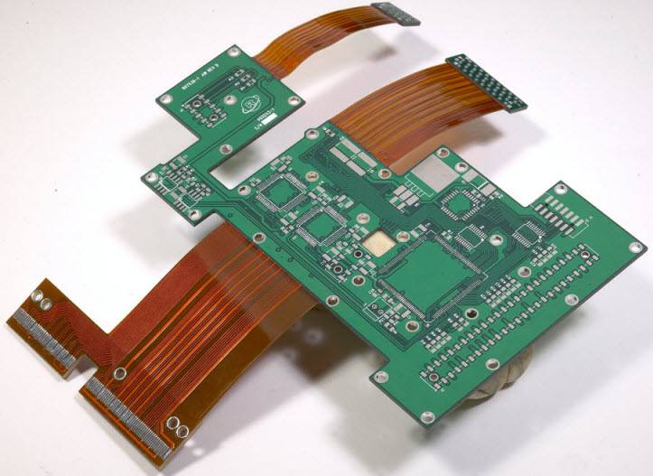
A rigid-flex board joins stiff FR-4 sections and thin polyimide flex tails inside one laminated structure. That single part replaces cables, connectors, and several separate boards. It also removes the assembly steps that used to join them. The benefit is real, but so is the risk. A small drift in lamination pressure or drill registration can scrap a whole lot. This guide walks through the decisions a buyer should check before release. It covers stackup, drilling, plating, assembly, and test, in the order the factory meets them.
Most rigid-flex problems start in the design file, not on the line. The flex tail is often drawn as a thinner rigid board, with the same copper weights and the same via rules. That shortcut fails once the part bends. Copper grain direction, coverlay openings, and the rigid-to-flex transition all need their own rules. A supplier who reviews these points early will flag them in a DFM report. A supplier who quotes from a Gerber viewer alone will find them during production.
The difference shows up in yield, not in the quote.
Stackup Choices
The stackup drawing is the first document to verify. It should mark which layers run through the flex zone and which stop at the rigid edge. Adhesive layers, coverlay thickness, and stiffener locations belong on the same drawing. Ask for the flex bend line to be shown. If the drawing treats the whole board as one uniform sandwich, the flex area will be too stiff or too fragile. Review this with your PCB design and layout team before tooling begins.
Material choice drives both cost and behavior. Polyimide flex cores handle heat and repeated bending better than polyester, and they suit solder assembly. The rigid sections can use standard FR-4, but the bond between the two material families needs a controlled press cycle. No-flow prepreg is common in flex zones because it limits resin squeeze into the bend area. Each of these choices adds a line to the drawing and a step to the process. Buyers should confirm them in writing rather than accept a verbal summary.
Lamination Control
Lamination is where rigid-flex yield is won or lost. Temperature, pressure, ramp rate, and dwell time must follow a recorded recipe for each stackup. Resin that flows too far leaves thin spots at the rigid edge. Resin that flows too little leaves voids and weak bond strength. Both faults may pass a visual check and fail later in thermal cycling. Ask the supplier how they qualify a new stackup. A first article with cross-section data is a reasonable answer.
Panel design also matters at this stage. Tooling holes, targets, and relief cuts must survive the press cycle without shifting. The rigid-to-flex transition is a stress point, so the copper there should be shaped to spread bending strain. Tear guards and fillets are simple features that prevent cracks from starting. They cost nothing in the layout and a great deal to add later. Buyers who see these details on the drawing can be more confident in the build.
Drilling Risk
Rigid-flex boards carry several hole types. Through-holes cross the full stack. Blind and buried vias stop at inner layers. Microvias may be laser drilled in the rigid sections. Each type needs its own registration window, because the materials move differently under heat. A drill program that works on a rigid board may miss on a flex core. Suppliers should show hole-wall quality and registration data at first article, not only at prototype.
Debris control is easy to overlook. Polyimide drills differently from glass-reinforced FR-4, and smeared resin can block a via or weaken a joint. Plasma desmear and careful hole conditioning help. So does a drill schedule that accounts for stack height and entry material. Buyers should ask whether the supplier drills flex cores in-house or sends them out. Outsourcing adds a handling step and a second registration risk. Neither is fatal, but both belong in the process review.
Plating And Imaging
Copper plating must cover hole walls evenly across a mixed-material panel. Thin plating in a flex via will crack under bending, even if it passes continuity test at the factory. Panel plating and pattern plating each have tradeoffs in thickness control. The supplier should state which method they use and how they verify hole-wall copper. Cross-sections from the first lot are the simplest proof. Without them, the buyer is trusting a claim rather than a measurement.
Imaging and etching follow plating. Trace width and spacing must hold across both rigid and flex zones, where copper adhesion differs. Undercut on a flex core can reduce conductor width more than expected. That matters for controlled impedance lines and for current-carrying traces in a bend area. Ask for coupon data if impedance is specified. If it is not specified, ask why not, because a flex tail often carries high-speed signals between two rigid sections.
Mask, Finish, And Assembly
Solder mask behaves differently on rigid and flex surfaces. The flex zone usually needs a coverlay or a flexible photoimageable mask instead of standard mask. Openings must clear the bend area and stay away from the transition line. Surface finish is a separate decision. ENIG suits fine-pitch parts and long storage. OSP is simple but short-lived. HASL is robust but adds thermal stress. The right answer depends on your components and your build schedule.
Assembly brings its own constraints. Flex tails are mechanically sensitive, so fixtures must support the rigid sections and leave the tails free. Reflow profiles should account for the extra thermal mass of a stiffened board. Handling rules matter too, because a bent tail can crack a via that tested fine. For volume work, plan the process with your high-volume PCB assembly partner before the first order. Early samples belong in a rapid PCBA prototyping cycle so faults surface cheaply.
Test Coverage
Electrical test proves continuity and isolation, but it does not prove a flex tail will survive field bending. A test plan for rigid-flex should combine bare-board test, in-circuit test, and functional test where the design allows. Visual inspection needs magnification and a defined defect list for coverlay wrinkles, edge cracks, and plating voids. Dimensional checks confirm the bend line sits where the drawing says. Each of these steps produces a record, and the record is what makes a repeat order predictable.
Traceability closes the loop. The factory should know which material lot, which press cycle, and which drill program produced each panel. When a field return arrives, that record shortens the investigation from weeks to days. It also shows whether a corrective action reached the next lot. Buyers should treat traceability as a normal part of the order, not as a special request. A supplier with a working quality management system will produce these records without argument.
Supplier Checks That Matter
Ask how the supplier qualifies a new stackup and who signs off the first article. Ask for cross-section data, hole-wall photos, and test records from a comparable build. Ask whether flex lamination is done in-house and how the press recipe is controlled. Ask how they handle engineering questions during production, and who answers them. These questions reveal more than a capability list. A supplier who answers with data is a different partner from one who answers with adjectives.
Component sourcing deserves the same scrutiny. A connector that changes plating, or a stiffener material with different thickness, can shift the assembly process without warning. Approved alternates and incoming checks keep that risk contained. Your component procurement process should cover this before the BOM is frozen. None of these checks is exotic. Together they separate a supplier who can build one good lot from one who can build the same lot again next quarter.
Pricing should follow the same logic. A low unit price that assumes a simple stackup will move once the flex zone is real. Ask for the quote to list stackup, finish, test level, and assembly scope as separate lines. That breakdown lets you compare suppliers on the same basis. It also shows where a cost reduction is safe and where it is not. Cutting test coverage or material grade to hit a target usually costs more in rework than it saves at the order.
The practical takeaway is simple. Treat the stackup drawing, the lamination recipe, and the test plan as one package. Confirm them in writing before tooling, and check the first article against them with real measurements. A rigid-flex program that starts with that discipline usually reaches volume without surprises. A program that skips it usually meets the same issues later, when they cost far more to fix.