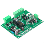
RMS to DC Converter Circuit Design
An RMS to DC converter produces a voltage proportional to the heating power of a waveform, which is the quantity that matters for a load. Average responding meters give the right answer only for a sine wave, and a true RMS converter gives it for any shape.
What the Measurement Means
The root mean square of a waveform is the square root of the mean of the square of the signal. It is the direct current that would produce the same heating in a resistor, and it is what a fuse, a motor or a loudspeaker responds to.
An average responding meter measures the rectified average and scales it by a factor chosen for a sine wave. On a waveform with a different shape the error can reach thirty percent or more, which is why a true RMS measurement is required for a distorted supply.
A true RMS converter computes the square, the mean and the square root, either with a thermal element or with an analog multiplier in a feedback loop. The logarithmic and exponential pair used in integrated converters does the same job with transistors.
crest factor and Its Limit
crest factor is the ratio of the peak to the RMS value of a waveform. A sine wave has a crest factor of about one point four one, and a narrow pulse train can exceed ten.
The converter has a limited dynamic range and its accuracy degrades at a high crest factor. The specification is usually quoted for a crest factor of three or five, and the error at ten is several times larger.
Where the waveform has a high crest factor, the input has to be attenuated so that the peaks stay inside the range of the converter. The attenuated signal then has a lower RMS, and the resolution of the following stage becomes the limit.

averaging capacitor and settling time
The averaging capacitor sets the time over which the mean is taken. A large capacitor gives a stable reading and a slow response, and a small one follows a changing level quickly with more ripple.
settling time is the time for the output to reach its final value after a step change in the input, and it is quoted for a specific change, often from zero to full scale. It is proportional to the averaging capacitor.
The choice follows from the measurement. A steady supply voltage is measured with a large capacitor and a slow reading, while a level that changes has to be followed with a smaller one and the ripple accepted.
Calibration and Accuracy
The converter is calibrated with a known direct current or a known sine wave, and the calibration removes the gain error of the multiplier. The offset is trimmed with no input, which is important because an offset in a squaring circuit produces a reading even with no signal.
The temperature stability of the calibration depends on the matching of the transistors in the multiplier, which is good on one die and poor between two. An integrated converter is therefore preferred over a discrete one for anything but the crudest measurement.
A converter chip usually has an internal trim or accepts an external one, and a production calibration is a matter of a minute with a stable source. The residual error is dominated by the crest factor behaviour rather than by the calibration.
Input Attenuator and Buffer
The input of an RMS converter has a limited voltage range, and a resistive divider brings a larger signal into it. The divider has to be compensated so that its ratio is the same at the highest frequency of interest.
A buffer before the divider presents a defined load to the source and a low impedance to the attenuator. Where the source is a current transformer or a shunt, the buffer also provides the conversion from current to voltage.
The input protection has to survive an overload, and an overload is the common failure of this measurement because the range of the instrument is set for the normal signal. A series resistor and a clamp diode protect the input without affecting the accuracy at the working level.
Frequency Response
The bandwidth of the converter is quoted for a stated error, and it falls at both ends. At the low frequency end the averaging capacitor sets the response, and at the high end the multiplier and the input buffer set it.
Measuring a switching waveform requires a bandwidth well above the switching frequency to capture the harmonics that carry the RMS content. A measurement made with too narrow a bandwidth reads low, and the error depends on the shape of the waveform.
A flat response across the band is not the same as a wide bandwidth. The specification that matters is the error over the frequency range the instrument claims to cover.
Thermal Converters
A thermal converter measures the RMS value directly by comparing the heating of a resistor with the heating produced by a known direct current. It is the most accurate method and the slowest.
The thermal element is delicate and it responds to the ambient temperature, so it is used in instruments rather than in industrial products. Its advantage is that it works for any waveform and any crest factor within its range.
Some designs use a thermal element in a feedback loop, so that the measurement is made at a constant temperature and only the current needed to maintain it is measured. The stability of that arrangement is much better than an open loop thermal sensor.
Verification and Faults
Verify the converter with a sine wave of known RMS and with a square wave, which has the same RMS as its peak. A square wave is a useful check because it has a crest factor of one and a well defined value.
Check the reading with no input. A residual reading is an offset error in the squaring stage and it has to be trimmed before anything else.
A reading that is correct on a sine wave and low on a distorted one indicates insufficient bandwidth rather than a calibration error. The release checks that keep such a channel consistent are collected in our PCB design release checklist, the assembly points in judging PCB quality, and the layout measures in our guide to mixed signal board design.
Process Control and Verification
On a design of this kind, settling time is the item that decides how the rest of the board is arranged. Where the requirement is not written down, the shop supplies its own default, and the default is chosen for the process rather than for the design. The measurements that matter are the repeatable ones: conductor width and spacing, annular ring, finished hole size, plating thickness and surface finish are all verifiable on a coupon that travels with the panel.
A first article check confirms that the process and the drawing agree on the points listed above, and that the coupon data supports the values used in the design.
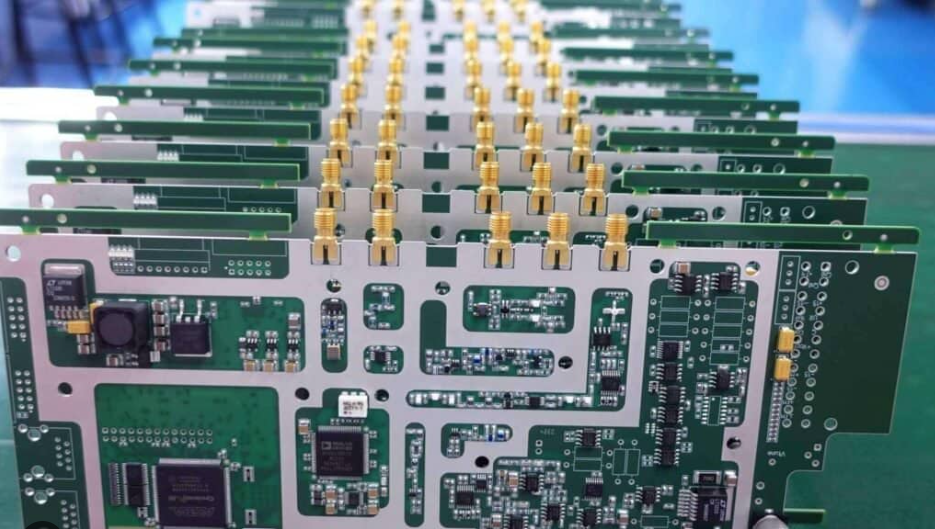
Where a measurement falls outside the expected window, the sample is retained so that the cause can be established before the balance of the batch is released.
FAQ
What is the difference between RMS and average? RMS measures the heating effect. Average responding meters scale the rectified average for a sine wave and are wrong for other shapes.
What is crest factor? The ratio of peak to RMS. A high crest factor reduces the accuracy of the converter and may exceed its range.
How do I choose the averaging capacitor? From the required settling time, accepting the trade with ripple on the output.