Satellite PCB vs Aerospace PCB: A Complete Guide to Design, Materials, Manufacturing & Applications
In the avionics industry, satellite PCBs and aerospace PCBs are often used interchangeably, and many procurement professionals assume they are merely different names for the same thing. However, from an engineering perspective, while both belong to the high‑reliability PCB category, they differ significantly in design philosophy, operating environment, material selection, manufacturing processes, and quality standards.
For example, a PCB used in a commercial airliner’s flight control system must operate reliably over a temperature range of –55°C to +125°C while withstanding engine vibration, electromagnetic interference, and pressure changes. In contrast, a PCB for a communication satellite or deep‑space probe must not only survive the intense shock and vibration of rocket launch but also operate continuously in vacuum, exposed to high‑energy cosmic rays, atomic oxygen, and extreme temperature cycles (approximately –180°C to +150°C) for more than a decade – with no possibility of maintenance or replacement.
This is why satellite PCBs represent the highest level of reliability in PCB manufacturing, with design margins, material performance, manufacturing precision, and testing standards far exceeding those of ordinary aerospace PCBs.
Whether you are developing communication satellites, CubeSats, avionics, UAV systems, or space communication modules, this guide will help you understand the technical requirements of each PCB type and provide a reference for your project selection.
What Is a Satellite PCB?
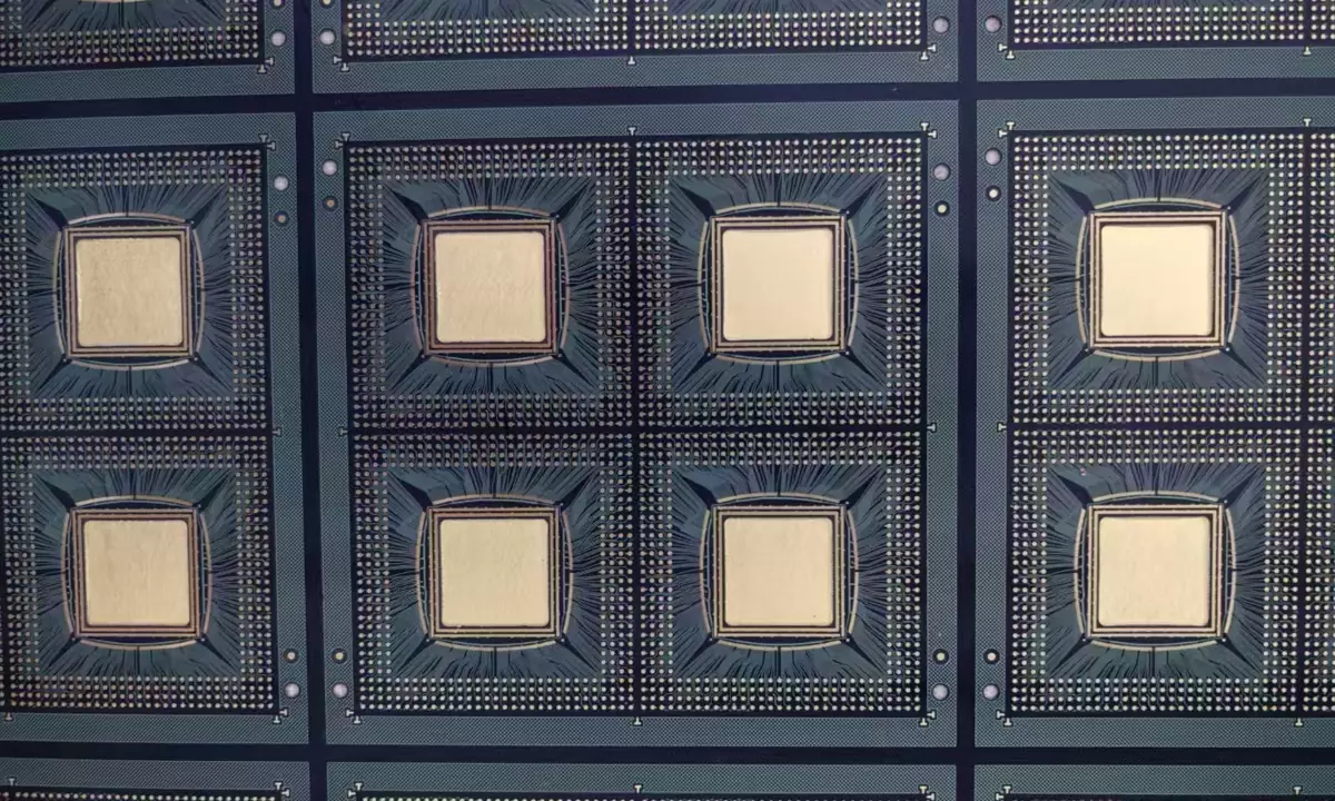
A satellite PCB is a high‑reliability printed circuit board specifically designed and manufactured for satellite and spacecraft electronic systems. It is the foundation of the entire satellite electronics architecture.
Applications include communication satellites, remote sensing satellites, meteorological satellites, BeiDou/GPS navigation satellites, military satellites, deep‑space probes, scientific experiment satellites, CubeSats, and commercial LEO satellites. These PCBs interconnect critical subsystems such as onboard computers (OBC), power management systems (EPS), RF communication modules, attitude and orbit control systems (AOCS), image processing units, payloads, and high‑speed data processors.
Since satellites are virtually unserviceable after launch, PCBs must exhibit extremely high reliability and long‑term stability. Many commercial communication satellites have design lives of 10–15 years, and geostationary (GEO) satellites may need to operate for 15–20 years or more.
Key Characteristics of Satellite PCBs
- Ultra‑high reliability: Any single solder joint, via, or trace failure can compromise the entire mission. Designs incorporate large safety margins and redundant circuits.
- Radiation tolerance: Space environments contain cosmic rays, high‑energy protons, electrons, and solar particle events that can cause single‑event upsets (SEU), single‑event latch‑up (SEL), memory errors, and dielectric aging. Satellite PCBs use radiation‑hardened components, strategic shielding, and layout techniques.
- Thermal stability: Satellites experience extreme temperature swings between sunlight and Earth’s shadow. Materials must have low CTE, high Tg, good dimensional stability, and excellent thermal conductivity.
- Vacuum compatibility: Outgassing of volatile organics can contaminate optical lenses, CCDs, IR detectors, and solar panels. Satellite PCBs use low‑outgassing materials.
- High‑density interconnect (HDI): To reduce weight and increase integration, most satellite PCBs employ HDI structures, laser microvias, buried vias, sequential lamination, and high layer counts (8, 12, 16, or even 24+ layers) with controlled impedance.
What Is an Aerospace PCB?
Aerospace PCBs are used in aircraft, UAVs, helicopters, missiles, rockets, and other avionics equipment. While they are also high‑reliability PCBs, their operating environment is different from satellites. Typical applications include flight control systems, avionics, radar, engine controllers, navigation, communications, UAV flight controls, military electronics, electronic warfare, and cockpit display systems.
The key advantage of avionics over satellite electronics is maintainability – aircraft have scheduled maintenance intervals, and electronic modules can be removed, replaced, or upgraded. Thus, aerospace PCBs place greater emphasis on maintainability, cost control, production consistency, and long‑life operation, whereas satellite PCBs have no repair opportunity and are designed with a more conservative philosophy.
Quick Comparison: Satellite PCB vs Aerospace PCB
| Aspect | Satellite PCB | Aerospace PCB |
|---|---|---|
| Operating environment | Space vacuum | Atmosphere |
| Cosmic radiation exposure | Mandatory | Generally not long‑term |
| Vacuum tolerance | Mandatory | Usually not required |
| Repairability | None | Maintainable |
| Service life | 10–20+ years | 5–20 years |
| Thermal cycling severity | Extreme | High |
| Launch vibration | Extreme | Not applicable (except rocket‑related) |
| Manufacturing cost | Very high | High |
| Failure tolerance | Near zero | Very low |
Environmental Differences
The operating environment dictates the design direction – this is the biggest difference between satellite and aerospace PCBs.
Satellite PCBs: Extreme Conditions
- Launch phase: High mechanical shock, random vibration, acoustic loads, multiple G‑forces, structural resonance. Every solder joint and via must be extremely robust.
- Vacuum: No air convection for cooling – heat transfer is only via radiation and conduction. Materials must not outgas and must maintain dielectric properties over decades.
- Space radiation: Long‑term exposure affects insulation, semiconductors, memory, FPGAs, and communication modules. Designs use radiation‑hardened components, grounding shields, redundant circuits, and careful layout.
- Extreme thermal cycling: Surface temperatures can swing from –180°C to +150°C repeatedly, causing CTE mismatch stress, solder fatigue, via degradation, warpage, and delamination. Satellite PCBs use high‑Tg polyimide, low‑CTE laminates, symmetric stack‑ups, balanced copper, and sometimes flex interconnects to relieve stress.
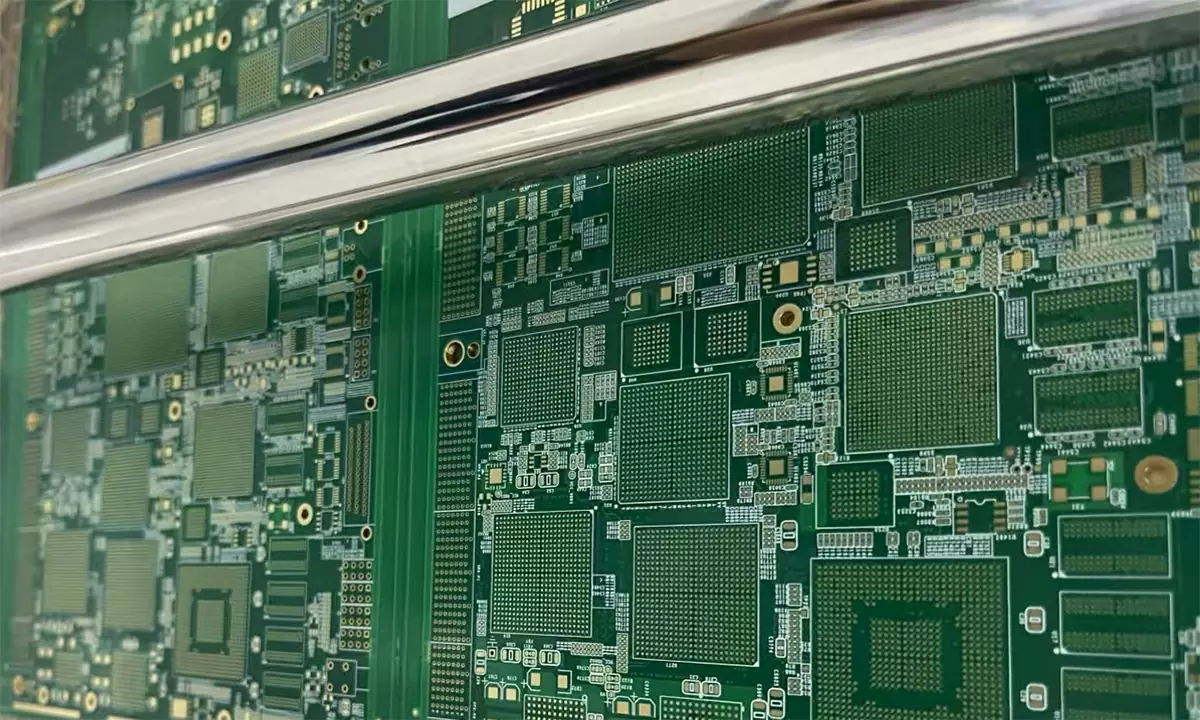
Aerospace PCBs: Harsh but Manageable
Avionics face low atmospheric pressure, engine vibration, humid heat, fuel/chemical exposure, EMI, lightning protection, and temperature changes (typically –55°C to +125°C). However, regular maintenance allows replacement and upgrades, so designs focus on maintainability rather than the extreme single‑shot longevity required for satellites.
Material Selection
Substrate materials determine reliability, thermal performance, mechanical strength, and high‑frequency signal integrity – making material choice one of the clearest differentiators.
- Satellite PCB materials:
- Polyimide: High Tg, excellent high/low temperature resistance, low CTE, chemical stability, high mechanical strength, long‑term reliability – widely used in onboard computers, power control, navigation, and HDI satellite PCBs.
- Rogers high‑frequency laminates: Stable dielectric constant, low loss, precise impedance control – used for Ka‑band, X‑band, and RF modules.
- PTFE: Ultra‑low dielectric loss, superior microwave performance, stable over wide temperature range – ideal for high‑frequency RF circuits.
- Ceramic (AlN, Al₂O₃): Extremely high thermal conductivity, low CTE, excellent insulation – for high‑power, high‑heat dissipation satellite electronics.
- Aerospace PCB materials: Typically high‑Tg FR‑4 or polyimide, with occasional Rogers for radar/EW applications, but generally lower complexity than satellite PCBs.
Stack‑Up and Design Differences
- Satellite PCBs: 8–24+ layers, HDI, sequential lamination, laser microvias, blind/buried vias, full impedance control, symmetric stack‑ups, balanced copper, low‑loss dielectrics. Hybrid stack‑ups (Rogers/PTFE for RF, polyimide for digital, high‑thermal for power) are common. Signal integrity, power integrity, EMC, crosstalk, clock sync, and thermal balance are meticulously designed.
- Aerospace PCBs: Typically 4–16 layers, standard multilayer or HDI (for high‑end avionics), high‑Tg FR‑4 or polyimide, isolated power/ground planes, local impedance control. Complexity is generally lower than satellite boards.
Reliability Requirements
- Satellite PCBs: Near‑zero failure rate, long‑life stability, thermal fatigue resistance, mechanical fatigue resistance, radiation hardness, stable electrical properties, low aging rate. Conservative design rules: wider traces, larger pads, thicker hole copper, redundant power and signal paths.
- Aerospace PCBs: High reliability but balanced with maintainability, testability, and upgradability. Scheduled maintenance allows module replacement, so extreme single‑shot longevity is not the primary driver.
Manufacturing Standards
- Satellite PCBs: IPC Class 3, IPC‑6012DS, NASA standards, ESA ECSS, MIL specs (as applicable), plus customer‑specific space requirements. Full traceability, process documentation, cleanliness control, and lifecycle quality tracking are mandatory.
- Aerospace PCBs: IPC Class 3, AS9100, IPC‑A‑610 Class 3, MIL standards, and OEM specifications. Requirements are also strict but less demanding in terms of vacuum, radiation, and extreme longevity.
Testing and Reliability Verification
Testing often constitutes a significant portion of the manufacturing cost.
- Satellite PCBs: Thermal cycling, thermal vacuum, humidity, random/sine vibration, mechanical shock, flying probe, fixture test, impedance, high‑voltage withstand, insulation resistance, TDR, Tg/CTE measurement, peel strength, low outgassing, AOI, X‑ray, microsection, solderability, and metallographic analysis. Multiple rounds of testing with full reports are typical.
- Aerospace PCBs: Similar tests but with less emphasis on vacuum and radiation, and more on vibration, temperature, and EMI.
2026 Cost Analysis (USD)
Satellite PCBs are among the most expensive PCB products due to advanced materials, complex processes, and rigorous testing. The following are budget estimates – actual quotes depend on design, materials, quantity, and test requirements.
| PCB Type | Prototype Price | Low‑Volume Price |
|---|---|---|
| Standard Aerospace PCB | $300–1,200 | $150–800/board |
| High‑Rel Aerospace PCB | $800–3,000 | $400–1,500/board |
| Commercial Satellite PCB | $2,000–8,000 | $400–1,500/board |
| Space‑Grade Satellite PCB | $5,000–20,000+ | Project‑based |
How to Choose a High‑Reliability PCB Manufacturer
For aerospace and satellite projects, selection criteria should go beyond price – focus on technical capability, quality systems, and engineering support.
- Engineering capability: Experience with high layer counts, HDI, high‑frequency/high‑speed, impedance control, hybrid stack‑ups, thermal management, and DFM support.
- Manufacturing capability: Precision mechanical and laser drilling, sequential lamination, high‑aspect‑ratio metallization, AOI, X‑ray, full electrical test, and impedance control.
- Quality system: Material traceability, IQC/IPQC/FQC/OQC, complete quality records, and traceability.
- Technical services: Stack‑up optimization, DFM analysis, material selection advice, cost reduction proposals, rapid engineering response, and support from prototyping to volume production.
Why Choose gopcb for High‑Reliability PCBs?
gopcb is a professional manufacturer specializing in high‑reliability PCBs for aerospace, satellite communications, industrial control, medical, automotive, and high‑frequency RF applications. Our core capabilities include high‑layer multilayer PCBs, HDI, Rogers high‑frequency, polyimide, heavy copper, impedance‑controlled, rigid‑flex, quick‑turn prototyping, and small‑to‑medium volume production with comprehensive quality testing and engineering support.
Explore our services: PCB manufacturing, prototype PCB assembly, turnkey PCB assembly, low‑volume PCB assembly, and high‑volume PCB assembly.
Whether for commercial LEO satellites, CubeSat projects, or complex avionics platforms, gopcb delivers customized, high‑reliability PCB solutions to reduce development risk and accelerate time‑to‑market.
FAQ
1. Is a satellite PCB considered an aerospace PCB?
Yes, satellite PCBs are a subset of aerospace PCBs, but they have much stricter requirements in materials, design, manufacturing, and testing due to the harsh space environment.
2. Can standard FR‑4 be used for satellite PCBs?
In some educational or commercial CubeSat projects, high‑performance FR‑4 may be used for non‑critical applications. However, for long‑duration or mission‑critical satellites, polyimide, PTFE, Rogers, or ceramic substrates are preferred for better thermal stability, low outgassing, and high‑frequency performance.
3. Why are satellite PCBs so expensive?
Due to high‑performance materials, complex manufacturing, stringent testing and certification, extensive documentation, small batch sizes, and extreme reliability requirements.
4. What is the typical design life of a satellite PCB?
CubeSat: 1–5 years; LEO communication satellites: 5–15 years; GEO satellites: 15–20 years; deep‑space missions: 10–20+ years, depending on mission design and environment.
5. Which materials are best for satellite PCBs?
Common choices include polyimide, Rogers high‑frequency laminates, PTFE, aluminum nitride (AlN), and alumina (Al₂O₃). The final selection depends on operating frequency, thermal dissipation, power density, mission life, and environmental conditions.
Conclusion
Although satellite PCBs and aerospace PCBs are both high‑reliability boards, they differ in operating environment, design goals, and manufacturing requirements. Aerospace PCBs serve avionics for aircraft, UAVs, and missiles – emphasising flight safety, long‑term stability, and maintainability. Satellite PCBs must withstand launch, vacuum, radiation, and extreme thermal cycling, operating for years without repair. They consequently employ more advanced materials, complex stack‑ups, tighter processes, and comprehensive validation.
For projects in space, satellite communications, defence electronics, and high‑reliability industrial equipment, partnering with an experienced PCB manufacturer like gopcb helps reduce risk, enhance reliability, and shorten project cycles.