




SMT Machine Sensors and Tool Change Guide
SMT machine sensors allow a pick-and-place machine to detect position, pressure, and safety conditions during every placement cycle. The sensor system is an important part of the whole SMT machine. Without sensors working together, the placement system cannot assemble boards reliably or safely.
Sensors provide the machine with feedback about the environment, the PCB, and the components. The controller uses this information to adjust movement, check the result, and stop the machine when an abnormal condition appears.
This guide explains the main sensor types on an SMT mounter and the tool change procedure used for a surface mount paper cutter.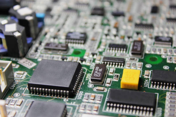
Pressure Sensors
A pressure sensor is mainly responsible for detecting and sensing the air pressure in the machine. When surface mount components are used, the air cylinder and vacuum generator have specific pressure requirements.
The pressure sensor monitors the compressed air supply. If the pressure is too low, the staff is immediately reminded to check the pressure source and the machine air lines.
Low pressure can prevent the nozzle from holding a component or prevent a cylinder from moving to the correct position. The machine should not be operated until the pressure is restored.
The pressure sensor also helps detect a vacuum problem at the placement nozzle.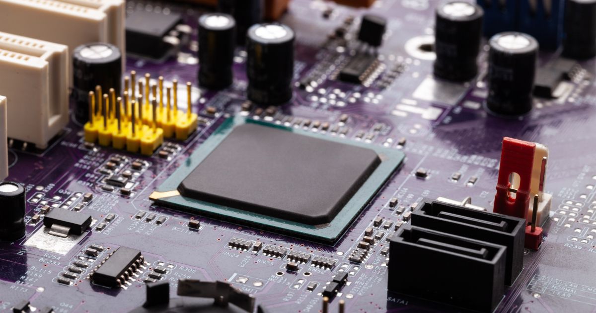
Position Sensors
A position sensor provides the position of the PCB to the SMT mounter system. It can also detect PCB components in real time and help the system complete the assembly task.
Position sensors are used for conveyor rails, board stops, and head movement. They tell the controller where the board is and when it has reached the correct clamping position.
If a board is not positioned correctly, the placement machine must not run. The position sensor prevents the head from placing components on a moving or misaligned board.
Position information has strict requirements because even a small error can shift every component.
Image Sensors
An image sensor provides the real-time working state of the SMT machine. It collects image signals such as the position of the PCB board, the component size, and the model of the installed component.
The universal coordinate system analyzes the images and processes the information to complete the assembly task.
Image sensors are used in the fiducial camera and the component camera. The fiducial camera finds the board position, while the component camera inspects the part before placement.
Clean lenses and proper lighting are necessary for the image sensors to work accurately.
Area and Safety Sensors
Area sensors are mainly used for real-time detection of safety problems. They are usually installed in each moving area of the SMT mounter.
When an operator or object enters the moving area, the area sensor detects the condition and stops the machine. This protects the operator from the placement head and conveyor.
The sensor should be tested before each shift. If the safety function fails, the machine should be locked out until the sensor is repaired.
Area sensors also prevent the machine from damaging a board or feeder when an obstruction is present.
Sensors Support the Complete Machine
The SMT machine sensors assist each other during the placement cycle. The pressure sensor confirms that air is available, the position sensor confirms the board location, the image sensor checks the component, and the area sensor protects the operator.
If one sensor fails, the machine should stop or alarm instead of continuing with incomplete information.
The sensor state can be shown on the machine display so the operator can identify which function is abnormal.
Regular sensor inspection is part of the preventive maintenance schedule.
Tool Wear and Replacement
A paper cutter blade is a common accessory on an SMT placement machine. The cutter separates the carrier tape or paper waste so the line remains clean.
The blade is a consumable. After continued use, it becomes worn and must be replaced to maintain a clean cut.
The replacement procedure should be followed carefully because the cutter is connected to the machine moving mechanism and air supply.
Before changing the blade, the operator should review the machine manual and confirm that the power and air supply can be controlled safely.
Prepare the Machine for Blade Change
The first step is to return the machine to its origin. The In tray should be moved to the fixed position, and the print head servo should be turned off.
The operator should use the manual handle to rotate the universal joint to the required angle, usually about 25 degrees, and then turn off the air supply.
Turning off the air prevents a sudden movement of the cylinder while the blade is being changed. The servo must remain off so the head cannot move unexpectedly.
The work area should be clean and well lit before the old blade is removed.
Replace the Blade
Loosen the screws on the fixing block and the adjusting block. Remove the old blade from the fixed blade holder first, then remove the blade from the moving side.
Install the new blade in the reverse order. The blade should be aligned so that it can cut paper cleanly without excessive force.
After the blade is installed, rotate the adjusting screw on the left side of the cutter to move the blade up and down. The blade should cut ordinary paper but should not be too tight.
Correct adjustment creates a blade overlap of about 1 millimeter and prevents damage to the blade or the cutter mechanism.
Tighten and Test the Cutter
Tighten the clamping block screws and the positioning block screws after the blade adjustment is complete. The cutter should move freely along its guide.
Use the manual handle to rotate the head back to its origin position. Then turn on the air supply and return the machine to its home state.
Test the cutter with a piece of paper before normal production. The cut should be clean and complete without leaving uncut fibers.
If the cutter produces a rough cut, check the blade overlap and the adjustment screw again.
Change to a Different Blade Type
When a different type of blade or cutter is installed, the change procedure may require additional adjustment. First replace the paper cutter as described above.
Check the blade to make sure it is open and that the tape width is correct for the new feeder application. The blade and cutter path should match the tape being processed.
Move the machine blade up and down and check the operation. The blade path should be appropriate for the tape and should not contact an adjacent component or fixture.
Adjust the push length of the connecting rod so that the blade travel is correct. Then adjust the stop pin and keep a clearance of about 0.5 millimeters where required.
After all adjustments, run a sample to confirm the new blade cuts the material correctly and no alarm appears.
SMT machine sensor and cutter maintenance should be included in the quality management schedule of an SMT PCB assembly factory. A machine in good condition places components more accurately.
The maintenance record should be connected with the PCBA testing data so that a change in machine behavior can be found before it creates defective boards.
Operator training and clear instructions protect both the equipment and the person performing the maintenance.
Common Sensor Faults
Sensor faults can stop the SMT machine or create incorrect placement. A dirty image sensor lens reduces the accuracy of component recognition. A misaligned position sensor may make the machine clamp the board in the wrong location. The operator should understand the display message for each sensor and know the correct response.
Before replacing a sensor, check the wiring, connector, and power supply. Many sensor faults are caused by a loose connector or a broken cable rather than by the sensor itself. The replacement part should match the original sensor type and mounting position.
After replacement, the machine should be tested at low speed. The sensor reading should be compared with the machine display so the operator can confirm that the signal is correct.
Machine Maintenance Planning
SMT sensor and cutter maintenance should be planned with the complete equipment schedule. The factory should record the working hours of each tool and replace the blade before it creates a poor cut. Sensor cleaning should be scheduled with the nozzle and camera maintenance.
The maintenance plan should be supported by quality management records and by the PCBA testing data from the line. If placement quality starts to change after a tool change, the maintenance action should be reviewed before the machine is used for full production.
The SMT PCB assembly process is more stable when sensors, blades, nozzles, and other machine parts are maintained on a clear schedule.
Conclusion
SMT machine sensors provide pressure, position, image, and safety feedback for the placement system. Each sensor helps the machine assemble boards accurately and stop before damage occurs.
Paper cutter blades and other machine tools are consumables that must be replaced according to the correct procedure. Returning to origin, turning off the servo and air, adjusting the blade, and testing the result protect the machine and the product.
With proper sensor and tool maintenance, the SMT machine remains reliable and productive.


