




SMT Placement Machine Operation Process and Setup
The SMT placement machine operation process begins long before the first component is picked. The machine must be set up with the correct PCB, feeders, nozzles, and program data so that every component can be placed accurately without damaging the board or the part.
A placement machine is the most technically advanced machine on an SMT line. Its speed, accuracy, board capability, and placement ratio often determine the capacity of the whole production system.
This guide explains placement machine types, operating principles, and the step-by-step process used to prepare and start an SMT placement operation.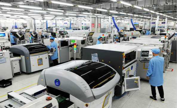
Types of SMT Placement Machines
Modern SMT placement machines are available for many applications. High-speed machines place ordinary chip components very quickly, while multifunctional machines handle large connectors, fine-pitch QFPs, BGAs, and unusual packages.
Small desktop machines are used for prototypes and low-volume production. High-speed modular machines are used for consumer electronics and other high-volume products.
Special placement machines are also available for LED boards, odd-form components, and flexible production requirements. Each machine is selected according to the component mix and required throughput.
Regardless of the type, every machine must perform the same basic tasks: pick a component, verify it, move to the correct pad position, and place it without damage.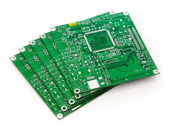
Machine Structure and Working Principle
An automatic placement machine is controlled by a computer system. The controller stores the product program, sends commands to the motors, and coordinates the feeder, conveyor, cameras, and placement head.
The placement head moves along the X and Y axes above the board. A vacuum nozzle picks the component from the feeder, and a vision system measures the component position and orientation.
The head then moves to the correct board coordinate and releases the component onto the solder paste. The Z axis controls the height of the nozzle so the part is pressed only enough to contact the paste.
Early machines used mechanical centering and moved more slowly. Modern machines use optical alignment, servo motors, and modular heads to achieve high speed and accuracy.
The system can be connected to other SMT equipment so that boards flow automatically from printing to placement and reflow.
Before Starting Production
The operation process starts by preparing the product process documents. The operator needs the assembly drawing, BOM, component placement list, and any special instruction for the product.
The PCB and components are selected according to the process schedule. Both should be inspected before use so that damaged or incorrect material is not loaded into the line.
If a PCB package has been opened, the operator should check whether it has absorbed moisture. Boards that have been stored for a long time may need baking before they can be processed.
Components should also be checked after opening. Moisture-sensitive devices are handled according to the SMT component management rules, including the correct bake time when the floor life has been exceeded.
Prepare Feeders and Components
Each component package is loaded into the correct feeder type. The operator should select the feeder based on the component tape width, pitch, and reel size.
The tape must be threaded through the feeder correctly so that the component is presented at the pickup position. The component center should be aligned with the feeder pickup center.
Feeder positions in the program should match the physical setup. If a component is loaded at the wrong station, the machine will pick and place the wrong part.
Empty reels, damaged tape, and incorrectly sealed pockets should be removed before production. A feeder problem can cause repeated missed picks and slow down the entire line.
Check Equipment Conditions
Before the machine is started, the operator should check the compressed air supply. The air pressure must meet the equipment requirement, usually about 6 to 7 kgf per square centimeter for the machine supply.
The area around the guide rails, placement head movement range, nozzle changer, and tray feeders should be free of obstacles. A loose tool or misplaced component container can cause a collision.
The machine should also be checked for correct nozzle installation, clean cameras, and a functioning conveyor. All safety guards and interlocks should be in place.
Recording the equipment check protects both the operator and the machine. Problems found during setup can be corrected before production starts.
Start the Machine
The operator starts the machine according to the equipment safety procedure. The control system should be switched on before the air and servo power are applied.
The operating air pressure is checked again after startup. Most placement machines require approximately 5 kgf per square centimeter during operation, depending on the machine model.
The servo motors are then enabled. All machine axes should return to their home or origin positions before any production movement is made.
Returning to origin establishes the machine reference point. If the machine is not homed correctly, the placement positions and conveyor movements will not be accurate.
Adjust the Conveyor Rail Width
The conveyor rail width should be adjusted according to the PCB size. The rails should be about 1 millimeter wider than the board so that the PCB can slide freely without falling or shifting.
If the rails are too narrow, the board will be pinched and may be damaged. If the rails are too wide, the board can move during placement and create positional errors.
After adjusting the rails, the operator should move a sample PCB through the machine to confirm that the conveyor height and width are correct.
Select the PCB Positioning Method
The PCB must be held in a fixed position while the placement head works. Most machines support pin positioning and edge positioning methods.
When pin positioning is used, locating pins are installed in the machine table according to the PCB tooling holes. Each pin should be centered in its hole so that the board can move up and down freely during clamping.
When edge positioning is used, edge blocks and stop blocks are adjusted according to the board outline. The board is clamped from the sides so it cannot move during placement.
The positioning method should provide a repeatable reference for every board in the production lot.
Set Up Board Supports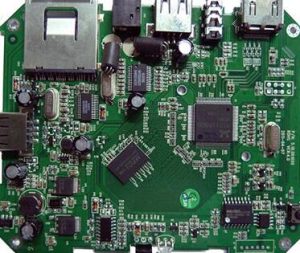
Support pins or board supports are placed below the PCB to prevent flexing during component placement. The board must be supported evenly so that no area bends when the nozzle presses a component.
The supports are positioned according to the PCB thickness and outline. When the second side of a double-sided board is being assembled, the supports must avoid components already placed on the first side.
If a support is under an existing component, it can crack or move the part. The support layout should be reviewed before the second-side placement program is run.
Correct support reduces board vibration, prevents component damage, and improves placement accuracy.
Load and Verify the Placement Program
After the mechanical setup is complete, the operator loads the product program into the machine. The program should match the current PCB revision and component list.
The program is checked for feeder assignments, component libraries, nozzle requirements, and board fiducials. Errors should be corrected before the machine is allowed to run.
The operator then places a sample board or performs an online programming test. The first placement results should be inspected before the line is released for full production.
If components are shifted, rotated, or missing, the program or machine setup must be corrected before the next board is processed.
Run Placement Production
During production, the machine follows the program automatically. The conveyor brings each board into position, the board is clamped, and the placement head picks and places every component.
The machine monitors vacuum, vision, and servo status during the cycle. If a component is missing or a feeder error is detected, the machine should stop or send an alarm so that the operator can respond.
Production records should be reviewed at regular intervals. Missed pick counts, component discard rates, and placement errors can show a developing feeder, nozzle, or component problem.
The operator should confirm that the correct board is being processed and that the program has not been changed by accident.
Inspect the First Assembled Board
The first board after setup should be inspected even if the program was used before. Component position, orientation, and solder paste contact should be checked visually and under magnification.
After reflow, the board should be inspected again for bridges, opens, and misalignment. The X-ray method may be required for BGA components.
If the first article passes, the production lot can continue. If defects are found, the placement process should be corrected before more boards are made.
Machine Changeover and Maintenance
When the product changes, the placement machine must be set up again with new feeders, components, nozzles, and program data. The changeover should follow the same preparation process as the first setup.
Nozzles and feeders should be cleaned and inspected during changeover. Cameras and calibration targets should be cleaned according to the maintenance schedule.
Preventive maintenance keeps the machine accurate and reliable. Air filters, vacuum pumps, rails, and drive systems should be checked at the recommended intervals.
Operator training is also important. People who understand the machine setup and safety rules can prepare boards faster and solve small problems before they stop the line.
Process Integration on the SMT Line
Placement is one step in a complete SMT line. Solder paste printing, placement, reflow, and inspection must be balanced so that no step becomes a bottleneck.
A professional SMT PCB assembly service plans the line for the actual product mix. High-speed machines may be dedicated to chips while a multifunctional machine handles connectors and BGAs.
The assembly process should be supported by PCBA testing and inspection after soldering. AOI, X-ray, ICT, and functional test verify the result of the placement process.
For new products, the PCB design and layout should provide fiducials, pad geometry, and component spacing compatible with the placement machine capability.
A reliable PCB assembly partner should document the setup process, record first article results, and use quality management data to prevent repeat defects.
Conclusion
The SMT placement machine operation process is a structured sequence of preparation, startup, positioning, program verification, and production inspection. Each step protects the board and components from damage.
Machines have developed from low-speed mechanical equipment to high-speed optical placement systems. Modern systems are modular, flexible, and capable of supporting almost any SMT production requirement.
With correct setup and maintenance, a placement machine can place components quickly and accurately, giving the whole SMT line high yield and reliable output.


