Solder Ball and Solder Beading Control
A solder ball is a small sphere of alloy sitting on the board surface, usually beside a joint and often unconnected to anything. Solder beading is a related but distinct defect in which a ball is attached to the side of a joint or to a component termination. The two are frequently reported under one name, which is why corrective actions often miss: they have different origins, and one responds to a change in the printing process while the other responds to a change in the reflow profile. Separating them is the first useful step in controlling either.
Two Defects With Different Causes
A free ball on the surface is alloy that was never part of a joint. It typically comes from paste that was deposited outside the aperture footprint, from paste that spattered during reflow, or from a partial reflow on the stencil that later broke free. A beaded ball, attached to a fillet or a termination, is alloy that separated from a joint while it was liquid and then froze where it landed, which is a wetting and surface-tension effect rather than a printing one.
The distinction is visible under a microscope and it is worth recording. A board covered in free balls points to the stencil, the wipe and the paste. A board with a few beaded balls on the same component points to the pad geometry, the component finish and the profile. Treating both with the same fix, such as a longer soak, usually removes one and leaves the other, and the defect returns.

Where the Alloy Comes From
Paste deposited on the mask rather than in the aperture is the largest single source. It happens when the stencil is under-wiped, when the paste is too thin, when the squeegee pressure is too low to clear the stencil surface, or when a gasket seal between the stencil and the board is missing so paste is pushed under the foil. A board with a scattering of small balls across its whole area usually has one of those conditions, and the pattern of distribution tells which.
Vias are the second source. An untented via that passes through the board can carry paste or alloy to the opposite side during printing or reflow, where it forms a ball on the secondary surface. This is why a ball defect that appears only on the underside, and only near vias, is not a printing problem at all but a via treatment problem. The same mechanism explains balls that appear inside a cavity or under a shield.
Paste Slump and How to Measure It
Slump is the tendency of a printed deposit to spread before reflow. A paste with too much solvent, or one that has been warmed during storage or use, will spread on the pad and reach over the mask, leaving a thin film that forms a ball later. Slump is measured by printing a test pattern, holding it for a defined time at a defined temperature and humidity, and measuring the change in the deposit footprint.
The practical control is to keep the paste within its specified temperature window and to limit the time between printing and reflow. Paste that sits on the line for hours in a warm room will slump even if it was correct when the container was opened. Where the line cannot reflow within the working time, the paste should be replenished rather than left, and the interval should be written into the paste inspection routine rather than left to the operator.
Stencil Wipe Frequency and Under-Stencil Cleaning
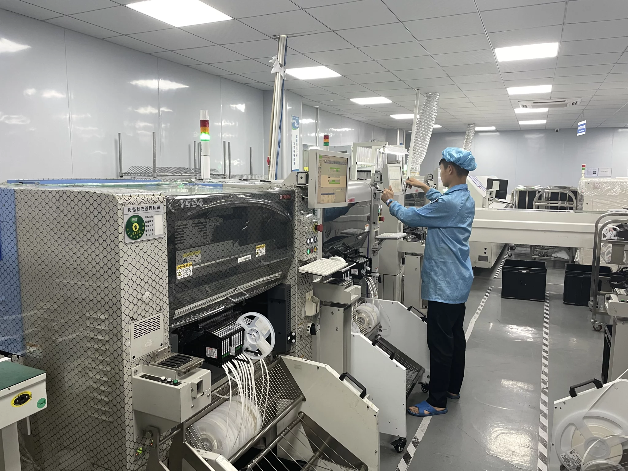
The wipe is the direct control on paste deposited outside apertures. The correct frequency depends on the aperture density and the paste: a dense board with small apertures needs a wipe far more often than a sparse one. Setting the wipe from a rule of thumb produces either a slow line or a board with balls, and the right figure is found by printing a representative run and inspecting the underside of the stencil between wipes.
Vacuum-assisted wiping and solvent wiping remove different things. A dry wipe removes paste; a solvent wipe removes the residue that the dry wipe smears, but leaves the stencil wet unless a drying step follows, and a wet stencil pushes paste under the foil. The sequence that works is usually a dry wipe with vacuum, followed by a solvent wipe only at longer intervals, with a short dry period before printing resumes. The stencil cleaning procedure should specify the sequence rather than only the interval.
Reflow Ramp and Flux Spitting
During the ramp, the flux in the paste boils and the volatiles escape. If the ramp is fast, the escape is violent and carries small droplets of alloy with it; those droplets land on the mask and freeze as balls. This is the classic cause of a board that prints cleanly and still comes out covered in balls, and it explains why the defect appears or disappears with a change of profile rather than a change of paste.
A slower ramp in the region where the volatiles are released, typically between the preheat and the soak, allows the flux to act without spitting. The reflow profile should therefore be checked against the paste maker’s recommended ramp, measured on the board rather than read from the oven display. Where the oven cannot slow the ramp without lengthening the cycle too much, splitting the preheat into two zones with a short hold often achieves the same result.
Vias, Through-Holes and Component Contribution
A through-hole that is not masked on the secondary side gives the alloy a path through the board. Paste or flux that enters the hole is pushed out of the far end as the board heats, and the alloy that follows forms a ball on the opposite surface. This defect is often reported as a printing issue because it is found after reflow, but the fix is in the mask artwork or in the plugging specification, not the printer.
Components contribute as well. A termination with a finish that wets poorly, or a body that has absorbed moisture, will eject alloy from the joint as it heats. The result is a bead attached to the component rather than a free ball. Where bead defects cluster on one component type, checking the moisture sensitivity level and the storage history of that part is more productive than changing the paste.
Inspection Criteria and Size Limits
Acceptance criteria for balls are usually written as a maximum diameter and a maximum number per unit area, with a stricter limit near fine-pitch components. The reason for the distance rule is that a ball close to a fine-pitch pad can be re-melted during a subsequent process and bridge onto the pad. Criteria should therefore state both the size and the proximity, and they should be applied to the finished assembly rather than to a coupon.
Inspection is visual under magnification, and the lighting matters because a ball on a dark mask is easy to miss with diffuse light. A low-angle light that produces a specular highlight on the alloy, and a moderate magnification of 10x to 20x, gives a reliable result. Where the criteria are tight, the count per board should be recorded rather than reduced to a pass or fail, so that a process drift is visible before the limit is reached. The inspection standard is the right place for both the limits and the method.
Corrective Actions in Order of Cost
The cheapest actions come first. Reducing the time between printing and reflow, raising the wipe frequency, and verifying that the paste has not been warmed during storage all cost almost nothing and often remove the defect. Next comes the profile, where a slower ramp or a hold in the volatile release region is a change to a program rather than to equipment. Only after those should the stencil or the paste be replaced.
When the paste is changed, the change should be to a formulation with a lower slump or a different flux system, and it should be evaluated on the same board and profile as before so the comparison is meaningful. Replacing the paste and the profile together produces a result that cannot be attributed, and the defect usually returns when one of the two is changed back. Recording the sequence of changes, and the ball count after each, converts a series of guesses into a controlled experiment.
FAQ
Do solder balls always indicate a defect? Not always. Many standards accept a small number of balls below a defined diameter in areas away from fine-pitch devices. What matters is that the criterion is written, that it is applied consistently, and that a ball near a fine-pitch pad is treated as a defect regardless of its size.
Can a ball be removed after assembly? It can be brushed off, but brushing can damage nearby joints and can push a ball into a gap where it is never found. Where the design has a risk of bridging, removing balls manually is a temporary measure, and the process should be corrected rather than inspected harder.
Does nitrogen reduce balling? It reduces oxidation and can reduce flux spitting slightly, because the surfaces wet more readily and the alloy has less oxide to displace. It is not a substitute for correcting the wipe and the ramp, and the benefit should be measured on the same board before the cost is accepted.