
Solder Joint Inspection Methods Guide
Solder joint inspection is a chain of methods rather than a single test. Each one sees a different part of the joint, and each one is blind to something that another can see. A visual check finds a bridge on a lead and misses a void under a package; an X ray finds the void and cannot measure the intermetallic layer; a cross section measures everything and destroys the board.
Why One Method Is Not Enough
The data sheet for a joint is a three dimensional object with an interface, a bulk and a surface shape. No single instrument sees all three at once.
The inspection plan therefore combines methods, and each method is chosen for the fault that it can detect rather than for its price.
The inspection plan is also a cost decision, because every method adds time to the line. The right balance is the cheapest combination that finds the faults which the product cannot tolerate, and it should be reviewed when the product changes rather than left unchanged for years.
The plan also has to suit the stage of production. A paste deposit is inspected before reflow, a joint after reflow, and a customer return after the product has been in the field.
A flying probe is a fourth option at this stage, since it reaches a net without a fixture and can check a connection that no optical method can see. The flying probe method is slower than a bed of nails and needs no tooling.
The mix of methods changes with the product, so a plan that was written for a leaded board may not cover a fine pitch assembly.
Visual Inspection
Visual inspection with a microscope or a magnifier is the oldest method and still the most versatile. It shows the fillet shape, the wetting angle, the presence of a bridge and the surface of the joint.
It is limited by the line of sight, so a joint under a package body or behind a tall component cannot be seen. On a fine pitch part the fillets are also too small to judge reliably by eye.
The method depends on the inspector, and the agreement between two inspectors is lower than most people expect. A written acceptance standard with photographs raises the consistency more than any instrument.
A visual check before reflow, on the paste deposit, is also a different skill from a check after, and the two are often combined in one station.
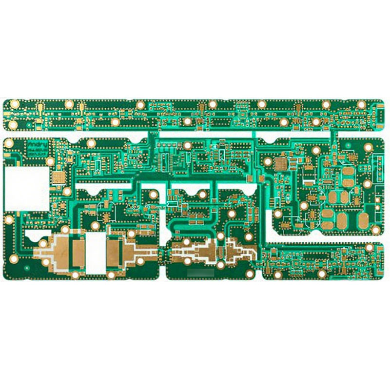
Automated Optical Inspection
An aoi system photographs the board and compares it with a programmed model. It has the same line of sight limits as a person, with the advantage of consistency and speed.
The system detects a missing part, a shifted part, a tombstone, a bridge on a visible lead and often a poor fillet by its shape. Its settings determine how many false calls it makes.
The programming is the largest part of the work, as described in the AOI guide, and a poorly programmed system will produce a stream of false failures that the operators learn to ignore. That is worse than no inspection at all.
The method is best at finding the defects that are visible, and it should not be relied on for the ones that are hidden.
X Ray Inspection
The comparison between the two optical methods and the X ray method is set out in the X ray and AOI comparison, which is the practical starting point for a ball grid array.
X ray passes through the board and shows the joint from above, which is the only practical way to see a ball grid array. The image shows the shape of the joint, the presence of a bridge and the voids inside it.
The limitation is that the image is a projection, so a feature at one depth is superimposed on a feature at another. A tomographic system can show one plane at a time and resolves the ambiguity at a much higher cost.
The void fraction is measured from the image, and the value depends on the threshold used by the operator. The method should be stated with the result for the number to be meaningful.
A void and a thin joint look similar in a two dimensional image, so a section is still needed to confirm what an unusual image shows.
Cross Section and Microsection
A cross section is the reference method. It shows the fillet, the intermetallic layer, the voids and the barrel in a single image, and it measures them.
It is destructive, slow and expensive, so it is used on a coupon or on a sample. The preparation quality decides the result, and a poorly polished sample hides more than it reveals.
The section also shows the things that no other method can, such as a crack at the corner of a barrel and a delamination under a pad.
The practice is described in the microsection material, and it is the method that settles a dispute because its result is a measurement.

Electrical and Functional Tests
An in circuit test measures the connections and the components, and it finds an open joint and a short. It does not find a joint that is connected but weak.
A functional test runs the product and finds the faults that affect the function, which may include a marginal joint that opens when the board is warm.
A daisy chain coupon with a continuous resistance measurement is the method that detects a joint that is degrading during a thermal cycle, and it is the only way to measure the fatigue life.
The signature of a marginal joint is a resistance that rises with temperature, and the solder defect guide lists the physical appearance that goes with it. A joint that is sound at room temperature and open at eighty degrees is the classic intermittent fault.
The electrical methods are complementary to the physical ones, since they measure the consequence of the defect rather than the defect itself.
Practical Rules
Choose the method for the fault that it detects, and accept that no single method covers the whole joint.
Write the acceptance standard with photographs and limits, so that two operators reach the same conclusion.
Use a cross section on the first article and on a coupon from each batch, and keep the image with the panel documentation.
Report the result with the method, the instrument and the operator, so that a second measurement can be compared with the first. A result without the method is an opinion, and the quality record should contain measurements rather than conclusions.
Record the method with every result, because a void fraction or a fillet judgement means nothing without the method that produced it.
FAQ
What is the best inspection method for a BGA? X ray, because it is the only method that sees under the package. A cross section is used to confirm what the image shows.
Can visual inspection find all the defects? No. It cannot see under a package or behind a component, and it depends on the inspector. It is best at surface defects on visible joints.
How is a void fraction measured? From an X ray image, as a percentage of the joint area. The value depends on the threshold used, so the method has to be recorded with the result.