Solder Joint Voiding Control in Reflow Assembly
Voiding in a solder joint is normal, and the argument is never about whether voids exist but about how much of the joint they occupy. A small amount of trapped gas has no measurable effect on reliability, while a large void directly reduces the area that carries current and heat.
Control therefore means knowing which joints are sensitive, measuring the voids that form, and adjusting the process where the measurement shows a problem. Treating every void as a defect wastes effort, and ignoring them entirely leaves a real risk in the joints that matter most.
Where the Gas Comes From
Every void starts as something that turns into gas at reflow temperature. Flux volatiles are the largest source, followed by the air that is trapped under a component when the paste melts, and by moisture absorbed into the laminate or into the component body during storage.
The distinction matters because the sources respond to different corrections. A volatile driven void follows the profile and the flux chemistry, a trapped air void follows the placement pressure and the paste deposit shape, and a moisture void follows the bake and storage history.
Flux Chemistry and the Profile
A flux that releases its solvent late, when the alloy has already formed a skin, traps that solvent inside the joint. A profile that soaks too briefly leaves the same solvent unvaporised until the joint closes, which is why an extension of the soak often reduces voiding more than any other single change.
The paste supplier specifies a profile window for a reason, and running at the edge of it is a common cause of intermittent voiding that appears on some panels and not others. Recording the profile with the void data is what makes the connection visible.
Paste Volume and Deposit Shape
A deposit that is too tall for the pad traps air in the corners as it collapses, and a deposit that covers an unfilled via draws gas from the barrel. Both problems are geometry, and both are solved by changing the aperture rather than the chemistry.
Where a large ground pad is involved, splitting the deposit into a grid of smaller apertures gives the gas a route out between the paste islands. This is the standard remedy for thermal pads, and it works because the gaps remain open until the alloy is molten.
Component and Board Moisture
A plastic package that has absorbed water releases it during reflow, and the vapour travels into the joint from below the part. The effect is worst on large packages with a large thermal pad, because there is more material to hold water and more joint area to receive the gas.
Baking the components and the boards before assembly removes the source, and the schedule should follow the moisture sensitivity level of the parts rather than a general rule. The handling and bake practice described in moisture sensitive handling is written for exactly this problem.
Measurement and Limits
X-ray is the standard method, and the figure that is compared against a limit is the total void area as a percentage of the joint area in the projected image. Because the image is a projection, the same void measured from another angle gives a different percentage, so the view has to be defined along with the limit.
Typical limits range from fifteen to twenty five percent for a thermally critical joint and are more generous for a signal joint that carries little current. Applying a thermal limit to every joint produces a rejection rate that the process cannot achieve and that the product does not need.
Reducing Voiding in the Process
The first lever is the profile, and specifically the soak and the preheat ramp that precede the melting point. A longer, gentler soak lets the flux work and the volatiles escape before the alloy closes over them.
The second lever is the deposit geometry, with segmented apertures on large pads and a reduced paste volume where the joint does not need it. The third is the atmosphere, since a nitrogen environment slows oxidation and gives the flux more time to act, although it does not remove gas that has already formed.
Vacuum and Pressure Assisted Reflow
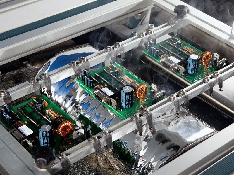
Vacuum reflow applies a reduced pressure while the alloy is molten, which draws the gas out of the joint before it solidifies. The result on a large thermal pad can be a reduction from a double digit void percentage to a low single digit figure.
The technique adds a process step and a machine, and it is usually reserved for joints with a defined thermal requirement. Where it is used, the same measurement method has to be kept, because comparing vacuum results with a non vacuum baseline is not meaningful.
Design Measures
Design decides how much voiding is even possible. A pad that is larger than the component land, a via that is open under the pad and a paste deposit that is oversized all create opportunities for gas to be trapped. Correcting them costs nothing after the fact.
Where a joint must be void free, the design should give the gas a route out: a segmented aperture, filled and capped vias and a pad that matches the land. These decisions sit with the fabrication and assembly data described in release checks.
Verification and Records
The verification is a sample measured at a defined interval, with the result recorded against the board identifier. Where the sample shows a change, the profile record and the paste lot are the first two items to compare.
Keeping the void data with the process parameters turns an intermittent complaint into a trend, and trends are what allow a process to be corrected before a customer sees the consequence.
Additional Considerations for This Build
Practical attention to solder joint voiding pays for itself here, because it decides whether the finished board behaves as the drawing intended. Where the requirement is not stated on the fabrication drawing or in the assembly notes, the shop has to assume a default, and that default is rarely the value the design was simulated with. Stating solder joint voiding explicitly, together with the tolerance that applies, removes the assumption and keeps the result predictable from batch to batch.
Deliberate attention to void limit pays for itself here, because it decides whether the finished board behaves as the drawing intended. Where the requirement is not stated on the fabrication drawing or in the assembly notes, the shop has to assume a default, and that default is rarely the value the design was simulated with. Stating void limit explicitly, together with the tolerance that applies, removes the assumption and keeps the result predictable from batch to batch.
Process Control and Verification
On a design of this kind, void limit is the item that decides how the rest of the board is arranged. Documenting the assumption is part of the design work, and a short note on the drawing prevents a question that would otherwise arrive a day later and cost a day of schedule. The process window is set by the narrowest step in the flow, so an improvement anywhere else shows up as margin rather than as yield until that step is addressed.
A short note on the drawing about handling, storage or packaging is often worth more than an extra decimal place on a tolerance.
Related reading: our fabrication notes, board quality and design release notes cover the same ground.
A first article check confirms that the process and the drawing agree on the points listed above, and that the coupon data supports the values used in the design.

Where a measurement falls outside the expected window, the sample is retained so that the cause can be established before the balance of the batch is released.
A first article check confirms that the process and the drawing agree on the points listed above, and that the coupon data supports the values used in the design.
Where a measurement falls outside the expected window, the sample is retained so that the cause can be established before the balance of the batch is released.
FAQ
Is any void acceptable? Yes. A void below the limit defined for that joint class has no measurable effect, and chasing zero voids is both expensive and unnecessary.
Does more paste cause more voiding? Often it does, because a taller deposit traps more air as it collapses, so reducing the volume can improve the result as well as the cost.
Can voiding be repaired? A joint with excessive voiding is usually reworked by removing and replacing the solder rather than by adding more, since adding solder does not remove the gas already trapped.
Why does voiding change between panels? The usual causes are profile drift, paste condition and moisture uptake, and all three are recorded by the process rather than by the design.