Spray Etching Uniformity Across a PCB Panel
Spray etching removes copper by impinging a fine mist of etchant onto the surface, and the uniformity of that removal is the specification that matters on a fine line panel. Two panels can leave the etcher with the same average line width and very different distributions, and the one with the wider spread is the one that fails at the impedance test or at the first article of the next revision.
Uniformity is a system property rather than a single setting. It is produced by the nozzles, the pressure, the oscillation, the chemistry and the panel geometry acting together, and it changes as the machine wears. Reading the panel as a map of the machine is the most useful habit in an etch area, because every systematic pattern on the panel has a mechanical or a chemical cause.
Why Uniformity Is the Specification
The etch rate at any point on the panel determines the line width at that point. If the rate varies by ten percent across the panel, the line width varies in proportion, and a design that holds its impedance tolerance only when the width is within five percent is already outside its window somewhere on the panel. The average says nothing about that board; the spread does.
The practical measure is the range and the standard deviation of a set of test traces distributed across the panel. A well maintained machine holds the etch rate within a few percent of the mean over the working area, and a machine with a blocked nozzle bank or a pressure imbalance shows a band of lines that are measurably thinner or thicker than their neighbours.
How Spray Etching Removes Copper
The etchant has to reach the surface, react with the copper, and carry the products away. In a spray system the droplets provide fresh etchant and their impact disturbs the boundary layer that would otherwise slow the reaction. Where the spray is weak, the boundary layer thickens, the local etchant is depleted, and the etch rate falls. Where the spray is strong, the rate rises until the chemistry rather than the delivery becomes the limit.
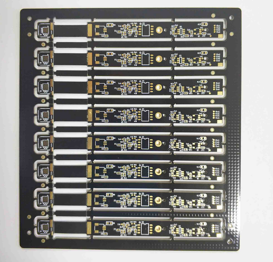
The reaction itself consumes oxidant and releases copper into the solution. At a heavily copper loaded area, such as a large ground plane, the local demand is high and the solution arriving at the adjacent fine lines is already partly spent. That is why the same machine produces a different result on a plane-heavy panel and a signal-heavy one, and why the compensation tables are built per product family.
Nozzle Layout and Spray Pattern
Nozzles are arranged in banks that oscillate across the panel, and the pattern of each nozzle overlaps its neighbours. The overlap is what smooths the individual cone patterns, and it is designed for a specific distance between the nozzle and the panel. A change in that distance, from a worn conveyor roller or a mis-set spray bar, changes the overlap and produces a periodic pattern of light and dark lines.
The nozzles themselves wear. A tip that has eroded delivers more flow at a lower velocity and produces a coarser pattern, and a partially blocked tip delivers less. Both are visible on the panel as a stripe that repeats at the pitch of the bank. Recording the nozzle change history and inspecting the pattern on an etch coupon at each service are the controls that keep the effect out of production.
Conveyor Speed and Dwell Time
Dwell time in the etch chamber is set by the conveyor speed, and the amount of copper removed is the rate multiplied by the time. The speed is the parameter operators reach for when the etch is short or long, and it is also the parameter that hides a change in the chemistry. Raising the speed to compensate for a fallen etch rate increases the undercut on the lines that are already marginal.

The speed should be verified against a marked panel at production load, because the conveyor behaves differently when it is carrying several panels. Loading patterns also matter: panels running nose to tail shield each other from the spray, and gaps between them produce a temporary surge of fresh etchant. The control is a loading rule that is written down and followed. Its role in the etch profile is described in the notes on etch factor and line width control.
Bath Chemistry and Etch Rate
The bath sets the ceiling on the etch rate, and the machine determines how much of that ceiling is reached at each point. The specific gravity, the temperature, the oxidation reduction potential and the free acid content are the four numbers that describe a cupric chloride etchant, and each of them moves the rate. The temperature is the most powerful and the easiest to hold, and a two degree change is visible on the next etch coupon.
Regeneration holds the chemistry steady as copper accumulates. Without it the specific gravity climbs, the rate falls, and the operator compensates with dwell time. The interaction between the bath and the machine is described in the notes on cupric chloride control and in the recovery side of the same loop in the notes on etchant regeneration.
Panel Loading and Shielding
Copper distribution on the panel changes the local demand on the etchant, and the etch rate falls wherever the demand is highest. A panel with a large plane on one side and fine lines on the other will etch unevenly even in a perfect machine, because the plane consumes the oxidant before the spray reaches the lines behind it. Rotating the panel or changing the side that faces the strongest bank is a partial answer.
The design answer is balanced copper. Thieving bars and a more even distribution of copper across the panel reduce the local variation, which is the subject of the notes on copper balance and etch uniformity. Where the design cannot be balanced, the fabricator compensates the artwork for the expected variation and accepts a wider tolerance on the affected lines.
Etch Compensation and Design Rules
Compensation is the difference between the artwork width and the finished width, and it varies with the line width, the copper thickness and the position on the panel. A single global compensation is a compromise that fits the average and misses both extremes. Where the uniformity is good, one number is enough; where it is not, the compensation is applied in bands across the panel.
The compensation is derived from measurement rather than from a table in a textbook. A test panel with traces of several widths at several positions, etched in production conditions and measured afterwards, gives the data for the product family. The trace width discipline that uses those results is described in the notes on fine line etching control.
Measuring Uniformity
The measurement is a set of line widths or resistance values taken across the panel on a dedicated coupon. Resistance is easier to measure in production and gives a good proxy where the trace geometry is known, while a microsection gives the absolute width and the wall angle. A coupon with nine measurement points arranged in a three by three grid is enough to detect a band pattern.
The results should be plotted as a map rather than tabulated as an average, because a map shows the shape of the problem. A gradient from one edge to the other points to a pressure or a nozzle issue, a repeating stripe points to the oscillation, and a patch in the centre points to the panel geometry. Each pattern has a different corrective action, and the map chooses between them.
Process Control and Records
The routine controls are the bath analysis, the temperature, the spray pressure of each bank, the oscillation amplitude and the conveyor speed, recorded per shift. The etch coupon result is recorded per lot, with the map kept as an image so that the shape of the distribution is preserved rather than reduced to a mean.
The maintenance record closes the loop. Nozzle replacement dates, spray bar adjustments and conveyor roller changes should sit beside the coupon maps, because the defect pattern that follows a maintenance event identifies the cause immediately. An etch area that keeps those two records together solves uniformity problems in hours instead of running experiments in the middle of a production order. The rinse that follows the etch has its own control, described in the notes on deionized water rinse.
FAQ
What uniformity is achievable in production? A well maintained spray etcher holds a few percent variation over the working area. Older machines with worn nozzles and coarse pressure control are two to three times worse.
Should the conveyor speed be used to trim the etch? Only within the window that the etch factor supports. Using speed for routine correction hides changes in the bath and increases the undercut.
Why do planes etch differently from lines? A large copper area consumes the oxidant locally and slows the reaction around it. Balancing the copper reduces the difference.