TVS Diode: Design Rules and Process Limits
A transient voltage suppressor is a diode that conducts when the voltage across it exceeds a threshold and absorbs the energy of the event. Choosing one is a matter of three numbers, and getting any of them wrong produces a circuit that either fails to protect or interferes with normal operation.
How the Device Behaves
The suppressor is a diode with a heavily doped junction that breaks down at a defined voltage. Below that voltage it is a small capacitor, and above it, it conducts a large current with a modest rise in voltage.
The response is fast, in the nanosecond range, which is the reason it is used for electrostatic discharge and for the faster part of a surge. It is not a fuse and it does not limit the energy of the event, it only diverts it.
The device is specified for a single pulse of a defined waveform, usually an eight by twenty microsecond current pulse. The peak pulse power rating applies to that waveform, and an event with a different shape has a different rating.
standoff voltage and Working Voltage
The standoff voltage is the highest voltage the device can hold without conducting appreciably. It has to be above the highest normal voltage on the line, including the tolerance of the supply and any legitimate signal swing.
Choosing it too close to the working voltage causes leakage and heating, and can clamp a legitimate signal. Choosing it too high leaves a larger voltage to reach the protected circuit, which may then need a lower clamping device further down the chain.
The standoff value is specified with its own tolerance, and a part with a nominal five volt standoff may begin to conduct at a lower value at high temperature. The worst case figure, not the nominal, is the one to compare with the maximum working voltage.
clamping voltage and the Protected Circuit
The clamping voltage is the voltage across the device at the peak rated current. It is always above the breakdown voltage, and it is the figure the protected circuit has to survive.
The protected circuit then needs a second device with a lower clamping voltage, or a series impedance between the two. A single suppressor in front of a sensitive input is rarely enough, and the layered arrangement is the standard approach.
The clamping voltage is also frequency dependent. Above a few tens of megahertz the package inductance dominates and the effective clamping voltage rises sharply, which matters for the fast edge of an electrostatic discharge.

peak pulse power and Energy
The peak pulse power is the product of the clamping voltage and the peak current for the specified waveform. It is quoted for a single event with a defined cooling time, and a repeated event at a high rate has a much lower rating.
The energy of the event divided by the duration gives the average power, and the die has a thermal mass that sets how much energy it can absorb. A long event at a modest current can therefore be more damaging than a short one at a high current.
Derating for temperature is essential. A device rated at one and a half kilowatts at twenty five degrees is rated far lower at a hundred degrees, and the derating curve in the datasheet is the source of the number.
surge protection in a Layered Scheme
A complete input protection has three stages: a device that takes the bulk of the energy, a series impedance that limits the current and creates a voltage drop, and a second device with a lower clamping voltage close to the protected circuit.
The series impedance is often a resistor, and it has to survive the current that flows during the event. A resistor that fails open leaves the second stage to absorb everything, and the failure is invisible until the next event.
Gas discharge tubes and metal oxide varistors handle much larger energies than a suppressor diode and are slower. Combining them is common: the slower device takes the bulk and the diode catches the leading edge that the other misses. The reasoning is the same as for any electromagnetic compatibility measure and is set out in our guide to EMI suppression design principles.
Capacitance and Signal Integrity
A suppressor diode has a junction capacitance of hundreds of picofarads to a few nanofarads. On a high speed data line that capacitance loads the signal and closes the eye diagram at the receiver.
Low capacitance versions use a diode in series with the suppressor, which reduces the effective capacitance at the cost of a higher clamping voltage. That is the standard solution for a data interface, and the capacitance figure belongs in the signal integrity budget.
Where the line is differential, two matched devices or a single array with matched channels are used. A mismatch converts part of the common mode into a differential signal, which the receiver then sees as noise.
Layout and Grounding
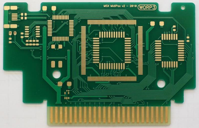
The device has to be placed with the shortest possible path to the source of the transient and to the reference it clamps to. A suppressor behind a long trace lets the trace inductance raise the voltage that reaches the protected circuit.
The ground connection is as important as the signal connection. The transient current flows through the ground path, and any impedance there develops a voltage that adds to what the protected circuit sees. A short, wide connection to a local ground plane is the requirement.
Protection devices belong at the connector, before any other component, and the protected circuit is placed after them. A layout where the suppressor is at the far end of the board provides almost no protection, however good the device is.
Verification and Faults
Verify the protection with a surge generator at the specified waveform and measure both the current through the device and the voltage at the protected circuit. The second measurement is the one that matters, and it is frequently several times the datasheet clamping voltage because of the layout.
Check the leakage current at the maximum working voltage. A device that is working close to its breakdown passes a current that heats it and eventually causes a failure that looks random.
A device that fails short circuit protects the circuit and takes the equipment out of service, which is the intended behaviour in a safety related design. A device that fails open leaves the circuit unprotected and is the more dangerous outcome, which is why the failure mode is part of the selection. The release checks that keep such protection consistent are collected in our PCB design release checklist, and the assembly points are listed in judging PCB quality.
FAQ
How do I choose the standoff voltage? Set it above the highest normal voltage including tolerance and temperature, but as low as the circuit can tolerate so that the clamping voltage stays useful.
Why is the measured clamping voltage higher than the datasheet value? Trace and package inductance. Move the device closer to the connector and shorten the ground return.
Can one TVS diode protect a whole board? Only against a common mode event. Each interface that leaves the enclosure needs its own device at the connector.