Fiducial: Design Rules and Process Limits
A fiducial is a small mark on the board that exists only to be seen by a camera. It is a patch of copper with a clear area around it, and the vision system of a stencil printer or a placement machine uses its centre to establish where the board actually is. Every subsequent placement is made relative to that reference, so an error in the fiducial is an error in every component position on the panel.
This article explains what makes a fiducial readable, the difference between panel, global, and local marks, where they belong on the layout, and the mistakes that quietly cost placement accuracy.
What Makes A Fiducial Readable
The mark has to present a high contrast edge to the camera and a stable centre. In practice that means a solid copper pad between one and three millimetres across, on a background that is uniform, with a clearance ring around it that is at least as wide as the pad diameter and that contains no traces, no vias, and no other feature that the vision system could mistake for an edge. The copper surface should be as flat and as uniform as the rest of the board, which favours a finish such as immersion gold over a hot air levelled surface that is uneven by nature.
Covering a fiducial with solder mask is the most common error, because it destroys the contrast that makes the mark visible. Where the mark is defined by mask rather than by copper, the opening has to be larger than the copper pad so that a ring of laminate surrounds the copper, and the same rule applies when the mask is used to define a target on a board where the copper cannot be exposed.
Panel, Global And Local Fiducials
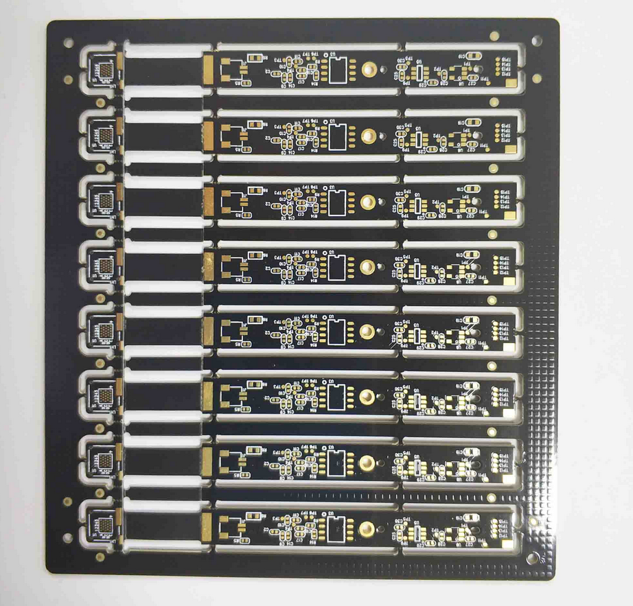
A panel fiducial is placed outside the individual boards, on the rails or in the tooling area, and it serves the operations that work on the whole panel: stencil printing, panel level inspection, and the first alignment in the placement machine. A global fiducial sits inside the board outline and locates that particular board after it has been separated, which compensates for the movement that the depaneling process introduces.
A local fiducial is a pair of marks placed close to a fine pitch component, usually within a few millimetres of the pad array, so the machine can align to the local area rather than to the board as a whole. Local marks matter for area array packages, chip scale packages, and connectors with a fine pitch, because the position of a single component within a board can differ from the board average by an amount that is significant at that pitch. Three levels of vision alignment are not always needed, but a board that carries both fine pitch arrays and coarse parts usually benefits from at least two.
Placement Rules And Clearance
The marks should be placed as far apart as possible on the board, because the angular error that the machine can resolve improves as the distance between them grows. Three marks are better than two, because a third point reveals a scaling error that two points cannot detect, and the arrangement should be asymmetric so that the machine cannot lock onto the pattern rotated through one hundred and eighty degrees.
Clearance is the second half of placement. A fiducial close to the board edge risks being damaged by the router or by the rail, and one placed near a tooling hole or a support pin can be shadowed by the fixture. The mark also has to survive everything that happens after fabrication: it should not sit where a label, a stiffener, a shield can, or a connector body will cover it, and it should not sit in a region that will be removed by a breakaway tab. Keeping it out of the component keepout area on the opposite side is equally important, because a part placed directly over a fiducial on the other side can confuse the camera.

Contrast, Finish And Imaging
The camera reads a fiducial by the difference in brightness between the copper and the surrounding material, so the finish and the illumination both matter. Immersion gold and immersion silver give a bright, uniform pad on a dark laminate, which is the easiest combination to read. A hot air levelled finish gives an uneven, rounded surface that reflects light in unpredictable directions, and an organic finish darkens with handling, so both require more careful lighting and a more tolerant algorithm.
The solder mask opening around the copper should be concentric and free of slivers, because a ragged opening edge presents a second edge to the vision system. Where the board is processed in a panel, the same fiducial has to remain visible after every step, which means the position must be checked against the placement of the mask artwork and against any coating that is applied before assembly.
Common Mistakes And Their Cost
The most expensive mistake is a missing local fiducial on a fine pitch array. The machine then aligns to the board average, and the placement error for that component is the sum of the board level error and the local distortion, which can exceed the tolerance of the paste deposit. The second most common mistake is a fiducial that the fabricator removes as an unused pad, which usually happens when the mark is drawn on a copper layer without a note explaining its purpose. A short note on the fabrication drawing prevents it.
Using a mounting hole or a plated through hole as a fiducial is also common and also wrong. The hole has a reflective ring, a dark centre, and a chrome or gold surface that varies with plating thickness, and its position is defined by the drill rather than by the artwork, so it carries the drill tolerance into every placement. The general pad and outline rules are described under pad design standards and board outline and mounting design.
Checking The Marks Before Production
The check is simple and should be formal. The fabrication drawing lists the fiducial positions, the diameters, and the mask opening, the stencil drawing shows the same marks with the corresponding openings, and the assembly program references them by name. The first article then verifies that the marks are present, uncovered, and readable, and that the machine is aligning to them rather than to a feature that merely looks similar.
The placement accuracy that the marks support is also a function of the pad geometry and the order in which components are placed, which is discussed under placement order and pad positioning. A board that is easy to align is one whose marks are deliberate, well spaced, well contrasted, and documented, and the cost of that discipline is a few square millimetres of copper.
FAQ
How many fiducials does a board need? Three global marks are the usual minimum for a machine that has to detect rotation and scale, plus a local pair for each fine pitch array that the board carries.
Can solder mask cover a fiducial? It can if the mark is defined by the mask opening rather than by copper, but the opening must be larger than the copper pad so that a ring of laminate frames it. Covering the copper entirely removes the contrast.
Why not use a tooling hole for alignment? Because its position is set by the drill and by the plating, not by the artwork, and its surface gives a weak and variable image. A dedicated copper mark is both more accurate and easier for the camera to read.